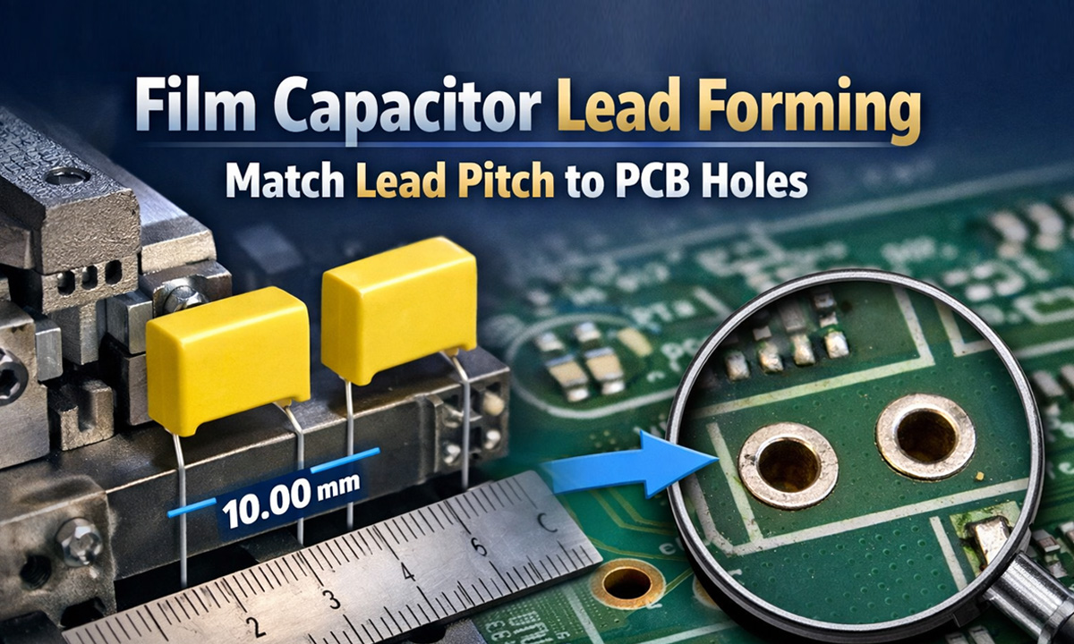
If you’ve ever tried to insert a film capacitor and the leads “almost” line up with the PCB holes, you know the pain: bent pins, cracked solder joints, slow assembly, and ugly rework. The fix is simple—set the lead pitch (the center-to-center distance between the two leads) to match the PCB hole spacing, and keep the bend consistent across every part.
Key terms (quick and simple)
- Lead pitch (P): Distance from one lead center to the other lead center after forming.
- Hole spacing: Same measurement on the PCB footprint (center-to-center of the two plated holes).
- Lead diameter: The wire thickness; it must fit the hole size with clearance.
- Standoff height: How high the capacitor body sits above the PCB (helps reduce stress and improves cleaning/solder flow).
The 4-step method to match leads to PCB holes
From the PCB design (or the physical board), confirm:
- Hole spacing (pitch): measure center-to-center
- Hole diameter: make sure it’s larger than the lead diameter (you want clearance, not a press-fit)
- Keepout / body clearance: ensure the capacitor body won’t collide with nearby parts
Tip: If you don’t have the design file, use calipers on the PCB. Measure from hole center to hole center (or measure outside-to-outside and subtract one hole diameter).
2) Confirm the capacitor’s “as-received” lead pitch and lead length
Film capacitors often come with a standard pitch, but it may not match your board (especially when you’re using alternate vendors). Check:
- Current pitch
- Lead length available for bending
- Distance from capacitor body to first bend (this matters for stress)
A “good” forming setup is not just pitch. Define three targets:
- Target pitch = PCB hole spacing
- Target standoff height: enough to avoid squeezing the body onto the board
- Bend location: keep the bend a small distance away from the capacitor body to reduce mechanical stress
Rule of thumb: Don’t bend right at the epoxy/body exit. Leave a little straight section so vibration and thermal cycling don’t concentrate stress at the body.
4) Validate with a simple go/no-go check
Before you run a batch, do a fast verification:
- Test insert into a sample PCB (or a pitch gauge)
- Leads should drop in without forcing
- Part should sit square, not “spring” sideways
- Solder fillets should form evenly (no lifted lead, no tension pulling the joint)
Common mismatch problems (and the real causes)
Problem A: Leads don’t enter holes unless you push hard
Likely causes
- Formed pitch is slightly off
- Leads are not parallel (twist during forming)
- Hole diameter too tight for lead diameter + plating thickness
Fix
- Tighten forming consistency (use a fixed die, not hand bending)
- Add a quick gauge check every X pieces
Problem B: Solder joints crack later (field returns)
Likely causes
- Leads are under mechanical tension because pitch is forced to fit
- Bend is too close to the capacitor body
- Standoff is too low (body pressed to PCB, stress transfers to joint)
Fix
- Match pitch precisely so insertion is “neutral”
- Increase standoff slightly and move bend away from the body
Problem C: Capacitor sits tilted after insertion
Likely causes
- Unequal lead lengths
- One lead has a different bend angle
- Leads formed with inconsistent “knee” position
Fix
- Control both lead length and bend geometry (a forming die solves this instantly)
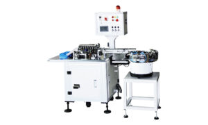
Hand forming is fine for prototypes. But once you care about speed, consistency, and yield, a forming machine becomes the easiest upgrade—especially for film capacitors used in power supplies and control boards.
If you’re forming radial parts (including metallized film capacitors), a pneumatic forming setup like this is commonly used for repeatable pitch and bend geometry: capacitor forming machine.
If you’re not sure which model/type fits your production (bulk vs tape, manual vs semi-auto vs fully automatic, different forming styles), use this: capacitor lead forming machine selection guide.
Quick checklist (copy/paste for the shop floor)
- Confirm PCB hole spacing (center-to-center)
- Confirm hole diameter vs lead diameter (leave clearance)
- Set target pitch = PCB pitch
- Set standoff height target (avoid body pressure)
- Keep bend slightly away from the capacitor body
- First-article check: insert into real PCB without force
- Periodic gauge check during production
FAQ
What’s the difference between lead pitch and hole pitch?
Nothing in practice—they must match. One is on the part (after forming), one is on the PCB footprint.
Can I “just spread the leads” during insertion?
You can, but it’s a reliability risk. If the lead is forced outward/inward, the solder joint becomes a spring-loaded stress point—cracks show up later under vibration or thermal cycling.
Does pitch matching matter if we use wave soldering?
Even more. Consistent insertion and neutral lead stress help reduce lifted leads, poor wetting, and inconsistent fillets.