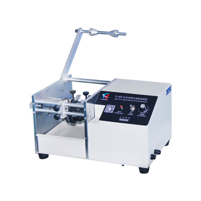
FL-602
Axial lead cutting & forming
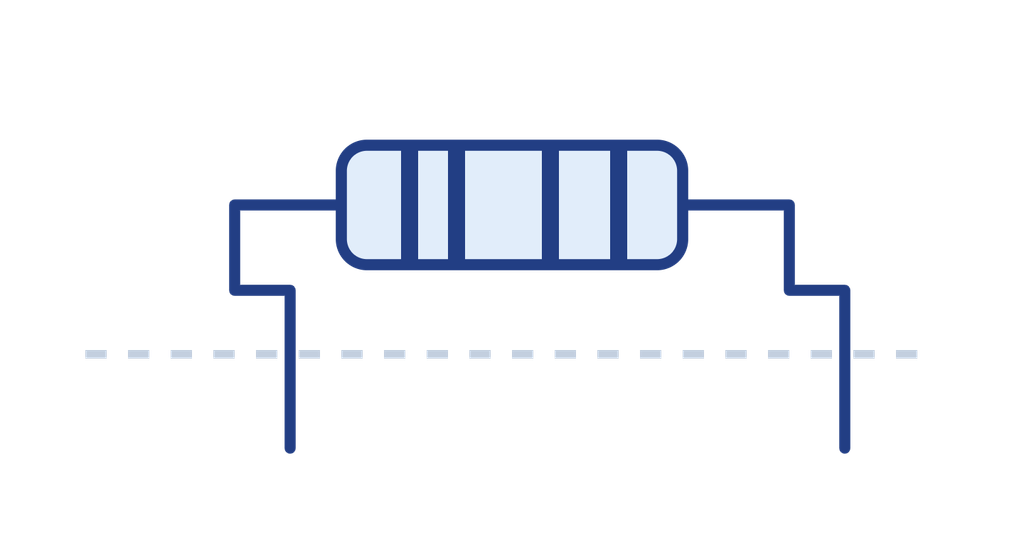
Axial lead cutting and forming with adjustable lead length and spacing. Available in U, F, and S configurations; confirm packaging compatibility before ordering.
View Details

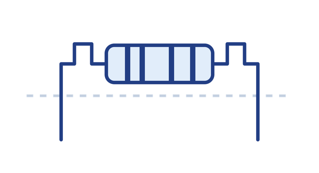
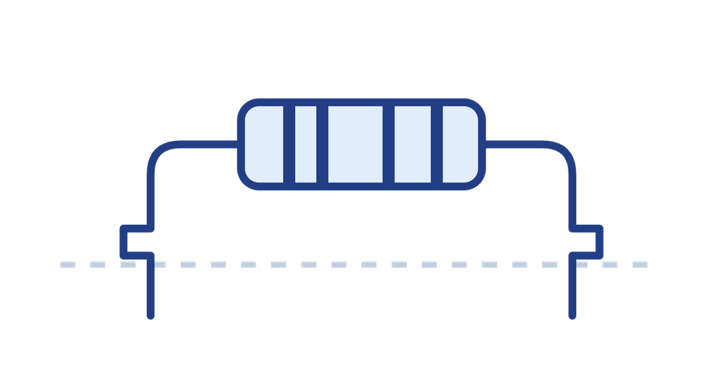

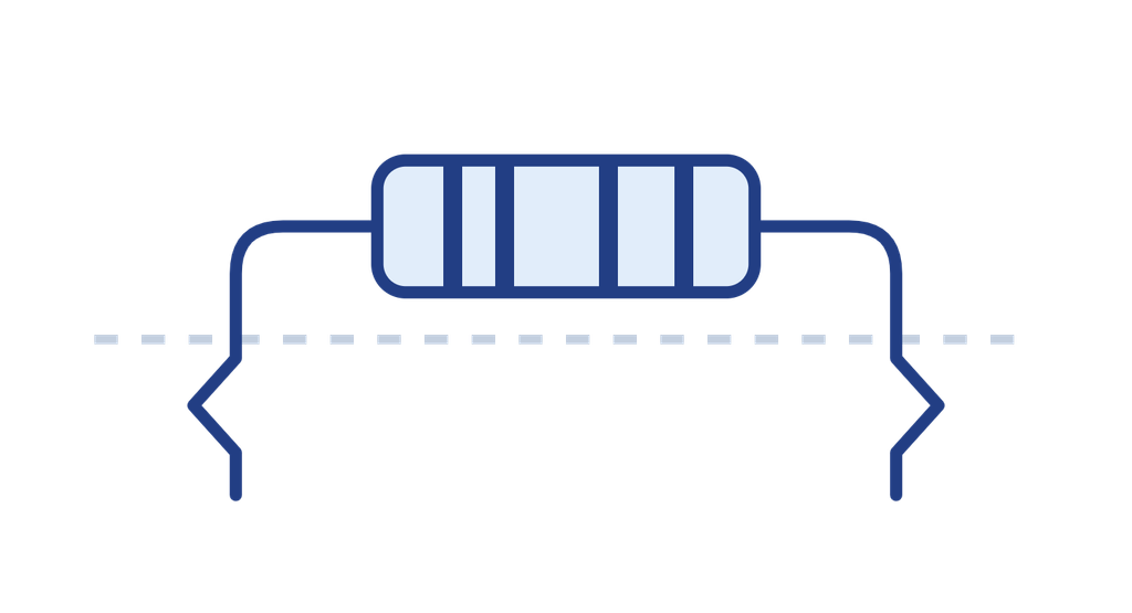
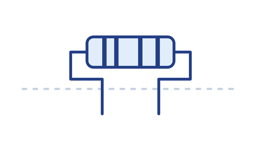
Compare models by feeding method and forming operation. Contact us to confirm tooling, component compatibility, and production capacity.
Axial lead cutting & forming
Axial lead cutting and forming with adjustable lead length and spacing. Available in U, F, and S configurations; confirm packaging compatibility before ordering.
View Details
Horizontal & vertical forming
Forms carbon film and metal film resistor leads. Interchangeable tooling supports horizontal and vertical mounting. Optional lead clamping is available.
View Details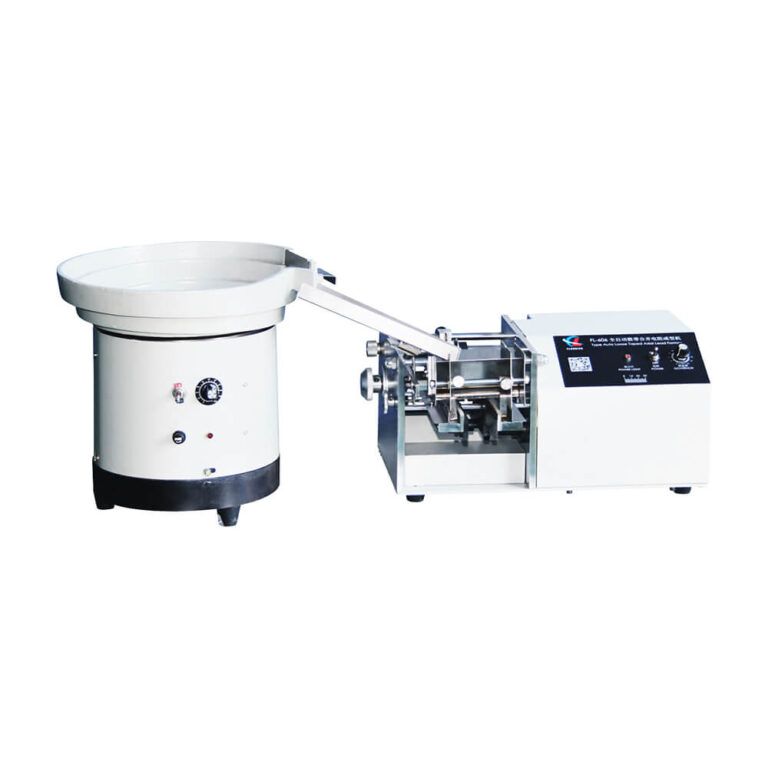
Automatic axial lead forming
Automatic axial lead cutting and forming with a vibratory bowl feeder. Confirm the feeding configuration for bulk or tube-packed components.
View Details
Bulk horizontal forming
Cut and form bulk axial resistors in a single operation for horizontal mounting.
View Details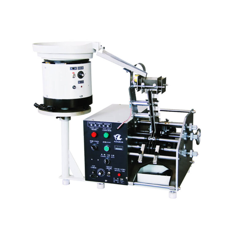
Horizontal resistor forming
Horizontal forming with dedicated bulk- or tube-feeding configurations and application-specific tooling.
View Details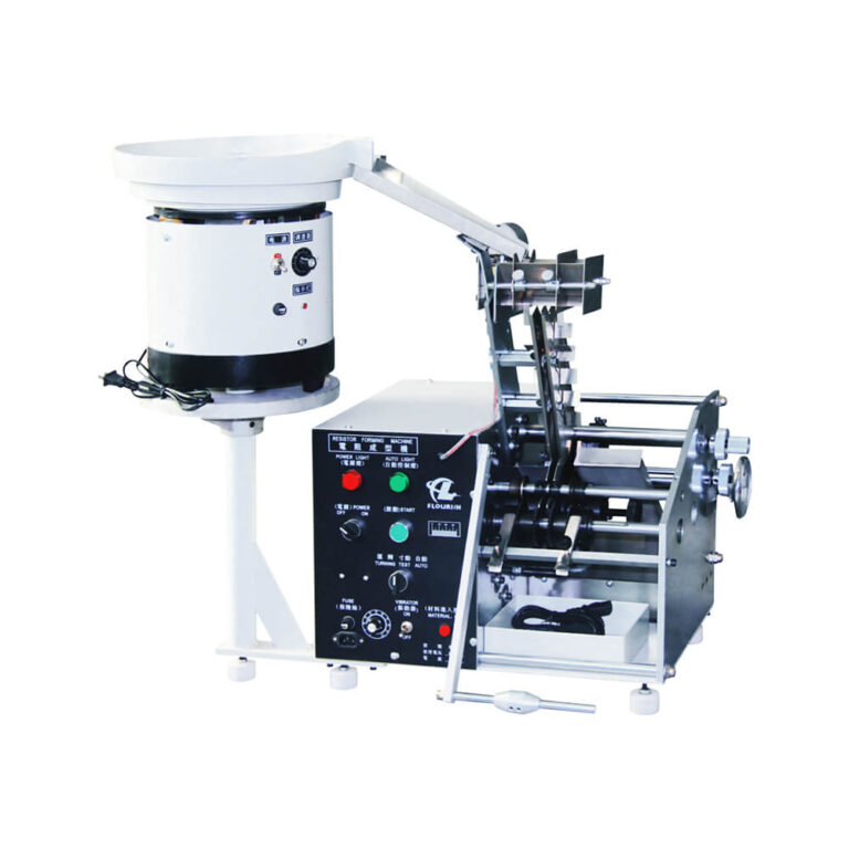
Vertical resistor forming
FK-series resistor lead forming equipment. Contact us to confirm the forming direction, feeding configuration, and tooling for your drawing.
View Details
Tube-packed vertical forming
Vertical lead cutting and forming for tube-packed axial components. Confirm tube dimensions and available lead length.
View Details
Resistor forming & welding
Integrates automatic feeding, cutting, bending, welding, and unloading for resistor assembly.
View DetailsAvailable lead forms, feeding methods, and production capacity vary by model and configuration. Submit your drawing and output requirements for machine selection.





| Issue | Possible Cause | Recommended Action |
|---|---|---|
| Incorrect lead spacing | Incorrect forming-pitch setting, worn tooling, component misalignment or lead springback. | Set the forming pitch according to the approved drawing. Inspect the tooling and component alignment, then measure the formed sample and verify its fit with the PCB. |
| Inconsistent cut length or mounting height | Incorrect positioning reference, unstable feeding, an improperly adjusted feed stop or worn cutting blades. | Confirm the measurement reference and adjust the feed stop. Inspect the cutting blades and compare the first formed parts with the approved sample. |
| Lead deformation or body coating damage | Rough tooling surfaces, burrs, excessive forming force, insufficient lead support or bending too close to the resistor body. | Inspect the tooling surface and clearance. Adjust the lead support and forming force, and maintain the required bend radius and distance from the resistor body. |
| Feeding jams or component misalignment | Incorrect feeder setup, mixed component sizes, damaged parts, tangled leads or improper feeding orientation. | Separate components by part number and remove damaged parts. Adjust the feeder guides, component orientation and feeding speed. |
| Incorrect dimensions after changeover | Incorrect tooling, retained settings from the previous part number or incomplete machine adjustment. | Install the correct tooling and load the approved settings for the new part number. Perform a first-article inspection before restarting batch production. |
Our resistor lead forming machines support a wide range of common axial resistor body sizes and lead specifications. To confirm compatibility, send us the resistor body dimensions, lead diameter, lead pitch, target lead length, packaging type, and required forming style. We can recommend the appropriate configuration and arrange a sample test if needed.
The machine is designed for repeatable cutting and bending so lead pitch, lead length, and bend angle remain consistent across batches. This helps reduce hard insertion, misalignment, uneven lead protrusion, soldering variation, and rework associated with manual forming.
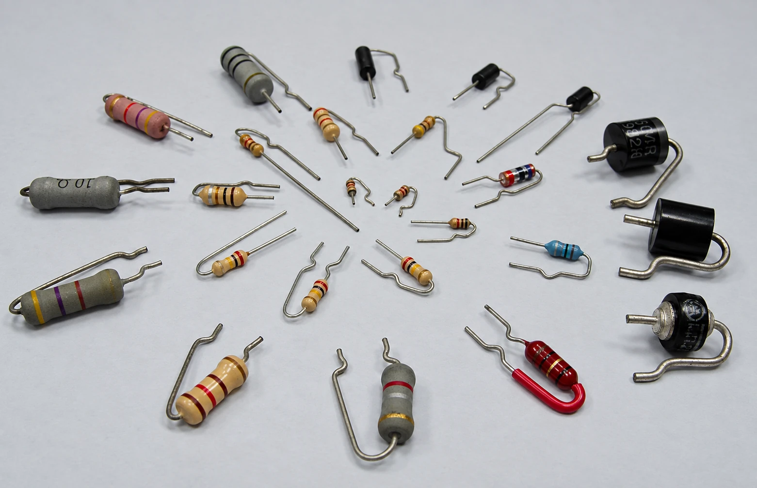
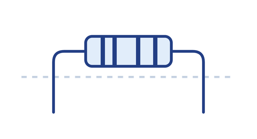
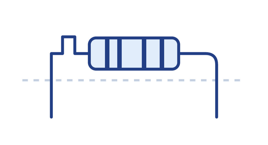
Depending on the machine and tooling configuration, available processes may include lead cutting, horizontal U-forming, vertical forming, standoff bends, stress-relief bends, and other application-specific shapes. Send us the target lead form, final pitch, and component drawing so we can confirm the appropriate tooling and machine configuration.
Routine maintenance includes cleaning, lubrication, and periodic inspection. Typical wear parts include cutting blades and forming tooling, depending on the lead material and production volume. We provide recommended maintenance and spare-parts guidance to help plan service and reduce unexpected stoppages.
Lead time depends on the machine configuration and required customization. We confirm the production schedule after the component samples, forming specifications, and equipment configuration are approved. Remote installation guidance or on-site support can be arranged according to project requirements.
The price depends on the model, feeding system, tooling, component range, and additional operations. Submit a component drawing, packaging details, and production requirements for a quotation covering the equipment, options, spare parts, and shipping.
Manual equipment may be suitable for prototypes and small batches. Automatic equipment may be more suitable for regular production. Compare production volume, changeover time, labor requirements, dimensional tolerances, and total operating cost.
Contact us to arrange a forming test using your components and drawing. Evaluate lead dimensions, surface condition, and PCB fit against the agreed acceptance criteria. Confirm production capacity, changeover requirements, utilities, spare parts, and support in the equipment quotation.