
- Blog
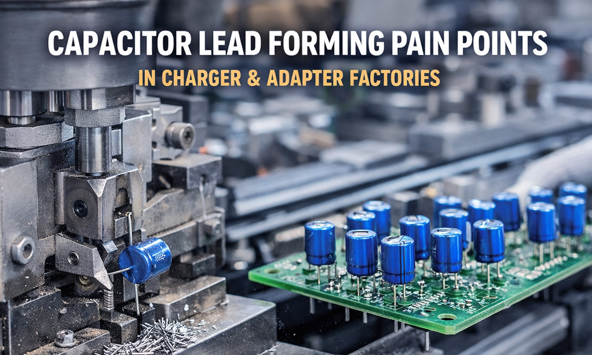
Capacitor Lead Forming Pain Points in Charger & Adapter Factories
- By tian81259@gmail.com
Charger and power adapter factories live and die by throughput and solder quality. You can have great SMT, clean wave solder profiles, and solid ICT—then lose yield because a “simple” through-hole capacitor doesn’t sit flat, pitches don’t match, or leads crack during forming. In high-volume charger/adaptor production, capacitor lead forming is one of those hidden bottlenecks that quietly creates rework, line stoppages, and long-term reliability risks.
Below are the most common capacitor forming pain points we see in charger/adapter plants—and what to do about them.
1) Lead pitch doesn’t match PCB holes (mis-insertion, tilted parts, bent pins)
What it looks like on the line
- Capacitors “fight” the holes during insertion
- Operators bend leads by hand to make them fit
- Parts sit tilted, or can’t sit flush on the board
Why it happens
- Pitch tolerance is drifting (tool wear, inconsistent feeding, operator setting differences)
- Mixed capacitor suppliers (same nominal pitch, different body/lead geometry)
- PCB hole tolerance + solder mask constraints reduce real insertion window
Impact
- Insertion slows down (or automation jams)
- Wave solder defects increase due to poor seating and inconsistent lead protrusion
- Higher risk of lifted pads when operators force components
Fix
- Lock your target pitch and tolerance (per capacitor family) and verify with go/no-go gauges
- Use dedicated tooling / quick-change setup per pitch to avoid “one setting fits all”
- If your product mix is heavy, consider equipment designed for stable pitch control and repeatability: Capacitor Lead Forming Machines
2) Cut length inconsistency (solder quality problems + cosmetic defects)
What it looks like
- Some boards have leads too long → risk shorts, poor clearance, ugly solder tails
- Some leads too short → weak solder joints, insufficient fillet, pull-test failures
- AOI flags “lead protrusion out of spec”
Why it happens
- Manual cutting or semi-auto setups rely on operator feel
- Knife wear, misalignment, or inconsistent lead positioning before cutting
- Capacitors arrive with variable lead straightness
Impact
- Wave solder variability (bridging, icicles, insufficient solder)
- More touch-up and rework, especially on dense charger boards
- Higher scrap risk after functional test if joints are marginal
Fix
- Define a cut-length spec tied to your soldering method (wave vs selective)
- Add a simple in-line check: lead protrusion sampling every X boards (or shift)
- For a deeper selection checklist, use this guide: 5 Must-Consider Factors When Choosing a Capacitor Lead Forming Machine (2026)
3) Lead cracks / micro-fractures after forming (field failures you don’t see today)
What it looks like
- Leads break during insertion or after wave solder
- “Intermittent” failures after vibration/thermal cycling
- Returns that don’t reproduce easily in the factory
Why it happens
- Over-bending radius (too tight) or wrong forming sequence
- Excessive mechanical stress from misfeeds or double forming
- Harder lead material or plating differences across suppliers
Impact
- Reliability risk (especially in higher-power adapters that run warm)
- Hidden cost: warranty + brand damage
Fix
- Use proper bend radius and avoid re-bending formed leads
- Reduce forming stress by ensuring consistent lead straightening before bend
- Standardize per capacitor type (electrolytic vs film, lead diameter, temper)
4) Low consistency across shifts (same product, different results)
What it looks like
- Day shift runs fine; night shift shows more insertion issues
- Different operators “tune” the same machine differently
- Setup drift after tool changes or maintenance
Why it happens
- No documented forming parameters (pitch, cut length, stand-off height)
- Setup relies on tribal knowledge
- Tooling wear isn’t tracked
Impact
- Quality escapes, unstable yield, extra rework manpower
- Hard to scale production without adding headcount
Fix
- Build a simple forming spec sheet per SKU family:
- Target pitch + tolerance
- Cut length (min/max)
- Stand-off height requirement
- Acceptable lead angle/parallelism
- Add tool-life tracking (knife, bending die) and planned replacement
5) Frequent changeovers due to high SKU mix (lost OEE)
Charger/adaptor plants often run many models and variants (different wattages, plugs, certifications). That usually means many capacitor specs, too.
Pain
- Changeover takes too long
- Wrong tooling used → immediate quality drift
- “Small” mistakes snowball into a whole pallet of rework
Fix
- Standardize capacitor families across designs when possible
- Use quick-change tooling and visual Poka-Yoke labels per pitch/lead diameter
- Keep pre-set tooling kits for top-running SKUs
6) Feeding and alignment issues (jams, bent leads, downtime)
What it looks like
- Leads get scratched, twisted, or bent before forming
- Jams during feeding cause stop-start production
- More burrs after cutting
Why it happens
- Capacitors aren’t straight or leads are tangled in bulk handling
- Incorrect guide/track settings for lead diameter or body size
- Build-up of debris near knives and dies
Fix
- Improve pre-alignment/straightening and debris control (cleaning intervals)
- Match guides to lead diameter and body size (don’t “run loose”)
Practical “Factory Checklist” for Better Capacitor Forming (Charger/Adapter Lines)
- Define spec: pitch, cut length, stand-off height, tolerances
- Control setup: documented parameters + quick verification gauges
- Reduce stress: correct bend radius and avoid rework bending
- Track tooling wear: knives/dies with planned replacement
- Stabilize feeding: alignment, guides, cleaning schedule
- Measure the right KPI: insertion issues, AOI rejects, solder defects, rework minutes
If you’re comparing equipment options or want to see proven configurations used in high-volume power electronics production, start here: Capacitor Lead Forming Machines. For machine selection logic and what specs truly matter, read: 5 Must-Consider Factors When Choosing a Capacitor Lead Forming Machine (2026).
Quick CTA
If you tell us your capacitor type (electrolytic/film), lead diameter, target pitch, and required cut length, you can usually narrow down the right forming method fast and avoid the most common yield killers.
Share the Post:
Related Posts


20 Years of Expertise, Trusted by Clients Worldwide
The Preferred Choice of Foxconn, BYD, and Huawei

