
- Industry News
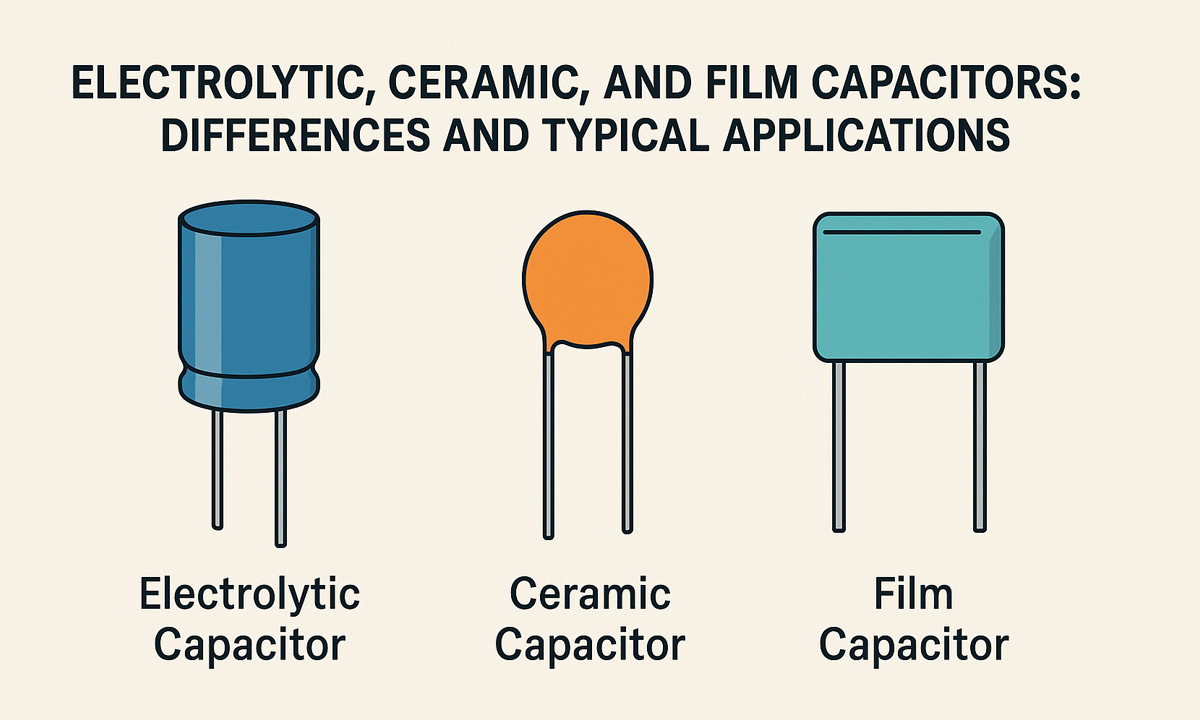
Electrolytic, Ceramic, and Film Capacitors: Differences and Typical Applications
- By tian81259@gmail.com
In modern power supplies, motor drives, new energy systems, and consumer electronics, electrolytic capacitors, ceramic capacitors, and film capacitors are everywhere. Yet many engineers still choose capacitors only by “capacitance and voltage,” ignoring dielectric material, ESR, ripple current, temperature behavior, and lifetime. That’s where hidden reliability and safety problems come from.
This guide walks through the three capacitor types from an engineering and manufacturing perspective:
- Basic structure and working principle
- Key parameter comparison with data tables
- Frequency behavior and typical applications
- How to choose the right type for your design
- How through-hole capacitors are processed with an electronic component forming machine, resistor lead cutting machine, and lead forming machine on the production line
The goal is to help design engineers, purchasing managers, and process engineers make more professional choices — not only at the schematic level, but also in mass production.
1. Basic Structure and Principles of the Three Capacitor Types
1.1 Electrolytic Capacitors
- Dielectric: Aluminum oxide (aluminum electrolytic) or tantalum oxide (tantalum electrolytic)
- Polarity: Usually polarized (marked + and –); reverse connection can destroy the part
- Structure:
- Aluminum foil (anode), paper separator, and electrolyte are wound together
- Inserted in an aluminum can, then sealed
- Advantages:
- Very high capacitance in a relatively small volume
- Cost-effective for bulk energy storage and low-frequency filtering
- Limitations:
- Higher ESR compared with ceramic and film capacitors
- Limited lifetime, highly dependent on temperature and ripple current
- Not suitable for high-frequency, high-dv/dt, or very high reliability applications on their own
Typical applications:
- Primary and secondary bulk capacitors in AC/DC and DC/DC power supplies
- Output filtering in chargers, adapters, LED drivers
- DC bus capacitors in industrial power modules (often combined with film capacitors)
1.2 Ceramic Capacitors (Including Disc and MLCC)
- Dielectric: Ceramic materials (NPO/COG, X7R, Y5V, etc.)
- Polarity: Usually non-polar
- Structure:
- Multiple ceramic layers with internal metal electrodes sintered together
- Through-hole style: round disc (ceramic disc capacitor)
- Surface-mount style: MLCC chips
- Advantages:
- Very low ESL and ESR — excellent for high-frequency decoupling and noise suppression
- Capacitance range from pF to µF
- High dielectric strength, wide voltage range
- Limitations:
- Capacitance can vary with voltage and temperature, especially for high-K dielectrics (e.g. Y5V)
- Large capacitance values with high voltage ratings can be expensive or bulky
Typical applications:
- Local decoupling and bypass around MCUs, FPGAs, DSPs, and high-speed logic
- High-frequency filtering and RF tuning circuits
- EMI suppression (for example, Y-type ceramic capacitors to ground)
1.3 Film Capacitors
- Dielectric: Polymer films such as polypropylene (PP), polyester/PET, etc.
- Structure:
- Wound or stacked metalized film
- Typically non-polar, rectangular “box” style is very common
- Advantages:
- Very low ESR and ESL — ideal for high ripple current and high-dv/dt environments
- Excellent insulation and self-healing characteristics
- Very long service life and stable electrical parameters
- Limitations:
- Larger volume compared with electrolytic capacitors of the same capacitance and voltage
- Higher cost per µF
Typical applications:
- PFC stages and DC-link capacitors in power electronics
- Snubber and clamp circuits for IGBTs and MOSFETs
- EMI/EMC filters, such as X- and Y-class safety capacitors
- DC-link for EV chargers, solar inverters, motor drives, and industrial inverters
2. Key Parameter Comparison (Data Tables)
The following tables provide typical engineering-level comparisons among electrolytic, ceramic, and film capacitors. Numbers are indicative ranges — always refer to the specific datasheet for design decisions.
Table 1 – Basic Electrical and Mechanical Parameters
| Parameter | Electrolytic Capacitor | Ceramic Capacitor (Disc/MLCC) | Film Capacitor |
|---|---|---|---|
| Typical capacitance range | 1 µF – 10,000 µF or higher | 1 pF – 1 µF (disc), up to tens of µF MLCC | 1 nF – 10 µF (DC-link film can reach hundreds of µF) |
| Typical rated voltage range | 6.3 V – 450 V or higher | 10 V – 2 kV (even higher for special types) | 63 V – 1,250 V or higher |
| Capacitance tolerance | –20% to +20% is common | ±5% to ±20% | ±1% to ±10% (precision versions available) |
| ESR level | Medium to high | Very low | Very low |
| Ripple current capability | Medium | Medium to high for high-frequency decoupling | High (excellent for ripple and pulse current) |
| Operating temperature range | –40 °C to +105/125 °C | –55 °C to +125 °C (common) | –40 °C to +105/125 °C |
| Expected lifetime | Limited (strongly affected by temp & ripple) | Very long | Very long |
| Volume (for same C & V) | Smaller than film, larger than ceramic | Medium | Largest among the three |
| Unit cost | Low | Low to medium (very low for small MLCC) | Medium to high |
Table 2 – Frequency and Application Characteristics
| Aspect | Electrolytic Capacitor | Ceramic Capacitor | Film Capacitor |
|---|---|---|---|
| Suitable frequency | Low to mid (tens of Hz – hundreds of kHz) | High (up to MHz range) | Low to mid-high, depending on construction |
| Main purpose | Bulk energy storage, low-frequency filtering | Decoupling, bypassing, high-frequency filtering | EMI/EMC filtering, DC-link, snubber, PFC |
| dv/dt capability | Medium | High | Very high (ideal for IGBT/MOSFET snubbers) |
| Noise performance | Average, ESR generates more noise | Excellent for sensitive analog/digital | Excellent for power stages and active filters |
These tables help you quickly decide which technology best fits your electrical and reliability requirements before diving into specific part numbers.
3. Typical Application Scenarios
3.1 Where Electrolytic Capacitors Shine
Electrolytics dominate in applications that need large capacitance at reasonable cost, especially at low to medium frequencies:
- Primary bulk capacitor in AC/DC power supplies, chargers, adapters
- Secondary output filtering for DC rails (e.g., 5 V, 12 V, 24 V)
- Bulk energy storage in industrial power modules
- Low-frequency coupling and smoothing in analog circuits
Engineering tips:
- Always check ripple current rating and expected temperature rise. Excess ripple shortens lifetime dramatically.
- For harsh environments (high ambient temperature or continuous full load), specify 105 °C or 125 °C, long-life series.
- In high-reliability power systems (EV chargers, industrial drives), combine electrolytics with film capacitors to share ripple current and improve lifetime.
On the manufacturing side, most electrolytic capacitors used in power supplies are radial leaded through-hole parts. For high-volume lines, plants typically use an electronic component forming machine to:
- Cut and bend leads to a consistent pitch
- Control lead length and component height above the PCB
- Prepare parts for wave soldering or selective soldering with minimum manual rework
3.2 Typical Uses of Ceramic Capacitors
Ceramic capacitors are the default choice wherever high-frequency performance and low impedance are needed:
- Local decoupling and bypassing around digital ICs (MCU, FPGA, DSP, ASIC)
- High-frequency noise filtering on clock lines, high-speed buses, and RF paths
- EMI suppression (e.g., disc-type safety capacitors between line and ground)
- Resonant and matching networks in RF and communication systems
Engineering tips:
- Place decoupling ceramics as close as possible to IC power pins, with short and wide return paths.
- For AC input EMI filters, use properly certified X/Y safety ceramic capacitors and follow creepage/clearance rules.
- When using through-hole disc capacitors in power boards or small appliances, pay close attention to insulation distance and mechanical stability.
In many power and appliance boards, disc ceramics are still common. Their leads often need to be:
- Cut to a defined length
- Formed into specific pitch and stand-off height
A lead forming machine is typically used for that job. Combined with a resistor lead cutting machine for resistors and other axial components, factories can keep overall lead length, insertion height, and solder fillet quality highly consistent across thousands of boards.
3.3 Where Film Capacitors Are Hard to Replace
Film capacitors are the go-to solution for high power, high reliability, and high dv/dt:
- DC-link capacitors in PFC stages, motor drives, industrial inverters, EV chargers
- Snubber and clamp circuits for IGBTs and MOSFETs
- AC input EMI filters, especially X- and Y-class safety capacitors
- Audio coupling and high-end analog filtering, where low distortion and stability matter
Engineering tips:
- For DC-link and snubber applications, evaluate ripple current, dv/dt rating, and self-healing behavior, not just capacitance and voltage.
- For safety film capacitors (X2, Y2), always use parts with the proper safety approvals and design the PCB to meet creepage and clearance requirements.
- For long-life industrial and automotive systems, film capacitors often provide a much longer lifetime than electrolytics, especially at elevated temperature and ripple.
Most film capacitors use box-type through-hole packages with rectangular leads. On a real production line, they are rarely soldered “as-is”:
- The leads are formed with a lead forming machine to match PCB hole spacing, stand-off height, and orientation (vertical or laid-down).
- An electronic component forming machine can batch-process film capacitors together with electrolytics and disc ceramics for maximum throughput and uniformity.
4. From Design to Mass Production: Through-Hole Capacitors and Lead Forming
Choosing the right capacitor type is only half of the story. In real factories — especially those building power supplies, industrial power modules, LED drivers, EV charger boards, and appliance control boards — engineers must also ensure that capacitors can be assembled efficiently and reliably.
4.1 Common Through-Hole Packages and Forming Requirements
Typical through-hole capacitor types include:
- Radial electrolytic capacitors
- Ceramic disc capacitors
- Box-type film capacitors (DC-link, X/Y safety capacitors)
These often leave the component manufacturer with straight leads. Before insertion and wave soldering, the leads must usually be:
- Cut (lead cutting)
- Control lead length to ensure proper solder fillet and avoid shorts or mechanical interference.
- Formed (lead forming)
- Adjust lead pitch to match PCB hole spacing exactly.
- Set component stand-off height for creepage distance, cleaning, and cooling.
- Taped (optional)
- For automatic insertion machines, parts may be taped and reeled after forming.
4.2 Why Use an Electronic Component Forming Machine?
An electronic component forming machine automates these steps for capacitors and other through-hole components:
- Consistent lead pitch and length across thousands of pieces
- Controlled stand-off height to meet insulation and thermal design targets
- Higher insertion efficiency, lower operator fatigue, and fewer soldering defects
- Less manual rework and re-forming at the workbench
For factories where capacitors and resistors share the same plug-in line, combining a forming machine with a dedicated resistor lead cutting machine is a cost-effective way to standardize all axial and radial parts.
4.3 Role of Lead Forming Machines in High-Reliability Products
In high-power and high-reliability applications (EV chargers, PV inverters, industrial drives), details like lead stress, component height, and creepage distances are tightly controlled.
A lead forming machine allows process engineers to:
- Define precise lead shapes (L-bend, K-bend, stand-off) for film capacitors and disc capacitors
- Avoid mechanical stress on component bodies that can cause micro-cracks or long-term failure
- Maintain consistent geometry so thermal expansion and vibration affect every board in the same way
This is where design choices (electrolytic vs ceramic vs film) and manufacturing solutions (forming, cutting, and taping) come together in a complete engineering system.
5. Practical Selection Workflow for Engineers
When selecting between electrolytic, ceramic, and film capacitors for a new design, you can follow this practical workflow.
Step 1 – Clarify the Functional Role
- Need large energy storage and smoothing?
→ Start with electrolytics or large film capacitors (DC-link) - Need local decoupling and high-frequency noise suppression?
→ Start with ceramics (MLCC or disc) - Need high dv/dt, high ripple current, and long life near switching devices?
→ Start with film capacitors
Step 2 – Define Key Electrical Requirements
- Required capacitance (C) and rated voltage (V)
- Frequency range and waveform (DC, AC ripple, pulse)
- Maximum allowable ESR and impedance at the main switching frequencies
- Ripple current and temperature rise targets
- Environmental temperature and expected product lifetime (5, 10, or 15 years, etc.)
For more detail on how to interpret manufacturer datasheets and tolerance curves, you can link to your own in-depth article such as an electronic component parameter guide.
Step 3 – Check Mechanical and Process Constraints
- Available PCB area and height limitation
- SMT vs through-hole (THT) mounting strategy
- If THT:
- Can components be pre-formed on an electronic component forming machine?
- Are lead length and stand-off height specified to ensure wave soldering quality?
- Can resistors, diodes, and capacitors share the same taping and forming process via a resistor lead cutting machine and lead forming machine?
Step 4 – Balance Reliability vs Cost
- For high-volume low-cost consumer products, a combination of electrolytic (bulk) + ceramic (decoupling) is usually sufficient.
- For industrial and new energy systems, film capacitors are often essential for DC-link, snubbers, and EMI filters, even if BOM cost is higher.
- In safety-critical systems, always consider derating, lifetime curves, and safety standards, not just initial cost.
For purchasing and process engineers, you can also reference (and internally link to) a separate article like a lead formers buying guide to understand how component forming equipment fits into the bigger picture.
6. Case Studies: Putting It All Together
Case 1 – 65 W Laptop Adapter
A typical 65 W notebook adapter might use:
- Input EMI filter:
- X2 film capacitor between line and neutral
- Y2 ceramic capacitors between line/neutral and ground
- Primary bulk capacitor:
- 400 V aluminum electrolytic capacitor (e.g., 100–220 µF)
- Secondary output filter:
- Low-voltage, high-capacitance electrolytics on the 19 V rail
- Multiple µF-level MLCCs near the controller ICs and feedback circuitry
On the production line:
- Electrolytics, film capacitors, and disc ceramics are pre-processed by an electronic component forming machine so that all parts share standard lead pitch and height.
- Axial resistors and diodes are handled by a resistor lead cutting machine, which unifies lead length and improves wave soldering consistency.
- Wave solder defects (insufficient solder, solder bridges, tilted components) are significantly reduced because every part enters the solder wave in the same mechanical posture.
Case 2 – EV On-Board Charger / DC Fast Charger Module
In EV chargers and high-power DC modules, the capacitor mix is different:
- PFC and DC-link:
- Large film capacitors for DC-link
- Electrolytics to increase total capacitance where needed
- Snubber and clamp circuits:
- High dv/dt film capacitors directly across IGBTs and MOSFETs
- Input and output EMI filters:
- X-class film capacitors, Y-class ceramics, and LC filter structures
Here, long-term reliability and safety are critical. Engineers not only choose the correct mix of electrolytic, ceramic, and film capacitors, but also define tight forming specifications and rely on a lead forming machine to ensure every safety capacitor consistently meets creepage, clearance, and mechanical stress limits in mass production.
7. Conclusion: From “Choosing a Capacitor” to Designing a Reliable System
To summarize:
- Electrolytic capacitors are the cost-effective workhorses for bulk energy storage and low-frequency filtering, but their lifetime depends heavily on temperature and ripple current.
- Ceramic capacitors are the first choice for high-frequency decoupling, noise suppression, and RF applications due to their low ESR and ESL.
- Film capacitors provide superior dv/dt, ripple current handling, and lifetime, making them essential in high-power, high-reliability circuits such as EV chargers, solar inverters, and industrial drives.
For real-world products, it’s not enough to select parts from a catalog. You must also think about:
- How these capacitors will be inserted and soldered on the PCB
- How to control lead length, pitch, and stand-off height
- How to achieve consistent quality across tens of thousands of boards
That’s where an electronic component forming machine, a dedicated resistor lead cutting machine, and a precise lead forming machine together turn your design decisions into a stable, repeatable, and highly reliable manufacturing process.
By understanding both the electrical physics of electrolytic, ceramic, and film capacitors and the mechanical realities of mass production, you can build power electronics that are not just functional on paper, but robust, safe, and profitable in the field.
Share the Post:
Related Posts


20 Years of Expertise, Trusted by Clients Worldwide
The Preferred Choice of Foxconn, BYD, and Huawei

