
- Blog
Key Parameters in LED Lead Forming: Lead Pitch, Lead Length, and Bend Radius
- By tian81259@gmail.com
When an LED doesn’t sit flat on the PCB, won’t enter the holes smoothly, or fails a downstream soldering/inspection step, the root cause is often one of three mechanical dimensions: lead pitch, lead length, or bend radius. Dialing these in is what separates “it forms” from “it forms consistently at scale.”
If you’re evaluating automation, start here: Electronic Component Lead Forming Machines and the Lead Forming Machine Product Archive (use these as hub pages for internal navigation).
Why these three parameters matter (more than you think)
LED lead forming isn’t just about shaping wire—it’s about controlling fit, stress, and repeatability:
- Fit: Pitch + length determine whether leads align with PCB holes and seat to the correct standoff height.
- Stress: Bend radius affects micro-cracks, plating damage, and long-term reliability.
- Repeatability: These dimensions must hold through tool wear, feed variation, and operator changes.
In most factories, a small drift in any one parameter creates a chain reaction: insertion issues → bent leads → solder defects → rework → yield loss.
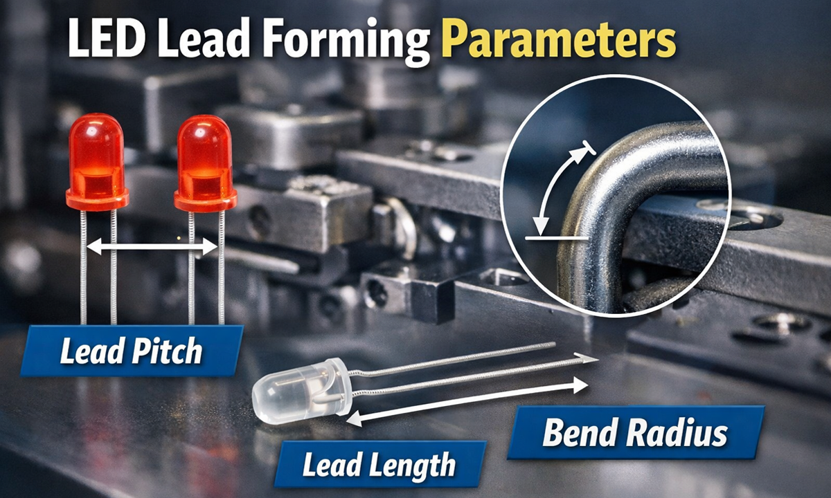
1) Lead Pitch: the “hole alignment” dimension
What it is
Lead pitch is the center-to-center distance between the two LED leads after forming. On through-hole LEDs, pitch must match the PCB hole spacing and the insertion tooling.
What goes wrong when pitch is off
- Too narrow: leads scrape hole edges, insertion force increases, pin bending happens.
- Too wide: one lead hits the pad edge or misses the hole, causing tilt or partial insertion.
- Pitch inconsistency (variation part-to-part): the worst case—automation becomes unstable even if the average pitch looks fine.
Practical pitch targets (typical examples)
You’ll commonly see PCB hole spacing designed around values like 2.54 mm and 5.08 mm (among others), but the real target is always your PCB spec and insertion method.
How to control pitch on a forming machine
Look for:
- Pitch adjustment mechanism that is rigid and repeatable (not “loosen → push by hand → tighten”).
- Tooling alignment reference (datums) so pitch doesn’t change during tool swap.
- Stable feed positioning so the LED body is always referenced from the same stop.
Internal link suggestion (replace with your exact LED model page if you have one):
2) Lead Length: the “seating + soldering” dimension
What it is
Lead length is the final length of the leads after forming (and often after trimming). This directly affects:
- Whether the LED sits at the correct height
- How much lead protrudes through the PCB
- Solder fillet quality and consistency
- Compatibility with wave solder fixtures or selective solder pallets
Common failure symptoms when length is wrong
- Too long: clashes with fixtures, causes shorts in dense assemblies, wastes solder, creates uneven solder fillets.
- Too short: insufficient protrusion, weak solder joints, higher risk of opens, or solder not wetting properly.
- Length variation: causes inconsistent standoff and inconsistent solder appearance—often flagged by AOI.
What usually causes length variation
- Inconsistent component seating against the stopper (body datum not stable)
- Blade wear / trimming tool wear
- Lead slip during forming (clamping force insufficient or surfaces contaminated)
- Feed pitch drift in the incoming taped/bulk parts
How to measure it correctly (so you’re not chasing ghosts)
- Use a simple go/no-go gauge for fast line checks.
- For troubleshooting, measure:
- lead length from a consistent body datum
- and record min / max / range, not just average.
Internal link suggestion:
3) Bend Radius : the “reliability + damage prevention” dimension
What it is
Bend radius is the curvature radius at the bend point. This is where mechanical stress concentrates—and where hidden damage can start.
Why bend radius matters in LEDs
LED leads are often plated, and some packages are sensitive to lead stress transferred into the epoxy body or internal bond structure. An overly tight radius can cause:
- Micro-cracks in plating
- Stress marks or weakened lead strength
- Increased risk of fatigue failure under vibration/thermal cycling
- In extreme cases, latent electrical failures after assembly
“Too tight” vs “too loose”
- Too tight radius: higher stress, higher damage risk, more springback unpredictability.
- Too large radius: may interfere with seating geometry or create insertion misalignment (depending on your formed shape).
How machines control bend radius
Bend radius is determined by:
- The forming die profile
- The distance and angle between forming surfaces
- Clamping stability (to prevent sliding that creates random radii)
If you’re forming multiple LED shapes or changing PCB designs often, prioritize machines with quick-change tooling and repeatable die positioning.
Internal link (category page example you already use on the site architecture):
How pitch, length, and radius interact (the part most teams miss)
These parameters are not independent. Two classic interactions:
Pitch ↔ Bend Radius
Changing bend radius (by swapping die/profile) can change springback behavior, which shifts pitch slightly—especially on harder lead materials. If you tune pitch first and later change tooling, your pitch may drift.
Length ↔ Pitch
If your process uses a body stop and then trims, any variation in seating against the stop can change the effective “bend location,” impacting both final length and pitch symmetry.
Practical takeaway: validate the trio together as one control plan, not three separate tweaks.
Recommended process control checklist (shop-floor friendly)
Setup validation (first article / first-off)
- Verify pitch with a gauge or caliper at multiple samples (e.g., 10 pcs)
- Verify length from a consistent body datum
- Inspect bend area under magnification for plating cracks/stress marks
During production (hourly / per lot)
- Track range (max-min) for pitch and length
- Record tool count or cycle count for trimming/forming tool wear
- Keep a golden sample that operators can compare visually and dimensionally
When defects appear
- Sudden pitch shift → check tool looseness, stopper position, feed alignment
- Length drifting over time → check blade wear, lead slip, clamp condition
- Random variation → check incoming part consistency + operator setup steps
What to look for in an LED lead forming machine (buying criteria)
If you want stable pitch/length/radius across long runs, prioritize:
- Rigid mechanical structure and repeatable adjustment
- Stable referencing (body stop and lead clamp design)
- Quick-change tooling with alignment datums
- Easy calibration process (so setup doesn’t rely on “operator feel”)
You can route readers to your product hub here:
(If you have a dedicated LED forming model page, swap it into the article as a primary internal link near the top.)
Final tip: write your spec like a manufacturer, not like a guess
For best results, define each parameter with:
- A datum (where you measure from)
- A target value
- A tolerance (acceptable range)
- A measurement method (gauge/caliper/vision)
- A sampling plan (how often, how many)
That’s how you turn forming from “trial and error” into a controlled process.
Share the Post:
Related Posts


20 Years of Expertise, Trusted by Clients Worldwide
The Preferred Choice of Foxconn, BYD, and Huawei

