
- Blog
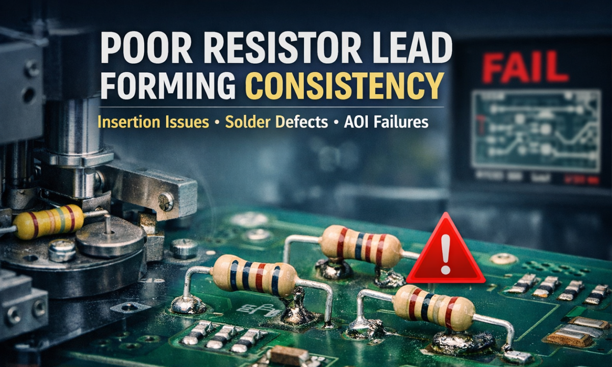
What Goes Wrong When Resistor Lead Forming Consistency Is Poor (And How to Fix It)
- By tian81259@gmail.com
Resistor lead forming looks simple—cut to length, bend to shape, hit the pitch. But when forming consistency drifts (even slightly), it creates a chain reaction: slower insertion, messy solder joints, higher AOI failures, more rework, and long-term reliability risks.
If you’re seeing random fit issues, uneven solder fillets, or “it worked yesterday” assembly headaches, inconsistent resistor forming is often the hidden root cause.
Need a stable process fast? Start with the right resistor lead forming machine, then match it to your parts using a resistor lead forming machine selection guide.
What “forming consistency” actually means
In production terms, consistency is repeatability across thousands (or millions) of parts. For resistors, it usually comes down to:
- Lead pitch (center-to-center spacing)
- Bend angle (90° that’s really 90°)
- Cut length (lead protrusion uniformity)
- Bend location (distance from the resistor body)
- Coplanarity / symmetry (both leads sit flat and aligned)
When any of these vary beyond your process window, downstream problems appear immediately—or worse, weeks later as field failures.
Common problems caused by poor resistor forming consistency
1) PCB insertion issues and slowed assembly
If pitch and bend position are inconsistent, resistors won’t drop into PCB holes smoothly. Operators start “helping” parts in, which causes:
- Bent leads, scratched solder mask, damaged plated-through holes
- Slower takt time and more line stoppages
- Higher dependency on operator skill (unstable output)
Typical symptom: “Some boards insert fine, some fight us.”
2) Wave/selective solder defects (and ugly joints)
Inconsistent cut length and lead protrusion change how solder wets and fills. You may see:
- Insufficient hole fill on longer/shorter protrusions
- Solder icicles, bridging, or spikes
- Fillet shape variation that triggers AOI rules
Why it matters: even if it “passes today,” marginal joints are less robust under thermal cycling and vibration.
3) Higher AOI failures and false rejects
AOI and post-solder inspection are built around repeatable geometry. Forming variation increases:
- “Lead length out of spec” flags
- “Component skew” or “offset” calls
- Unstable pass/fail thresholds (your inspectors end up tuning instead of inspecting)
Result: scrap risk rises—or you loosen thresholds and let bad boards slip through.
4) Mechanical stress on the resistor body (cracks, drift, early failure)
If the bend point creeps too close to the body, or angles vary, the lead can apply stress into the seal/epoxy area. That can cause:
- Micro-cracks (especially after thermal shock)
- Resistance drift over time
- Intermittent failures that are hard to debug
This is one of the most expensive outcomes because it shows up after shipping, not on the line.
5) Poor coplanarity → “floating” parts and uneven soldering
If both leads don’t sit flat, the resistor can “float” during soldering, creating:
- Tilted components
- Uneven solder fillets side-to-side
- Higher risk of touch-up and cosmetic rejects
6) Rework and yield loss
Once insertion and soldering become unstable, costs stack quickly:
- More manual touch labor
- More rework heat exposure (which itself hurts reliability)
- More line congestion and WIP
Even a small increase in defect rate becomes painful at scale.
Why consistency usually gets worse over time
If your forming started “okay” and then drifted, common causes include:
- Tool wear (cutters dulling, forming dies rounding)
- Loose guides / misalignment (vibration + time)
- Part variation (lead diameter, plating hardness, body length tolerance)
- Improper setup (pitch blocks not matched, stop position not locked)
- Maintenance gaps (chips/debris affecting positioning)
- Speed pushed too high (material springback increases, more bounce)
How to quickly diagnose forming inconsistency on the shop floor
Use a simple, fast check routine:
- Sample across time (start of shift, mid, end)
- Measure pitch, cut length, bend distance from body on 20–50 pcs
- Look for trend drift (not just random scatter)
- Inspect tooling for wear marks, burrs, or play
- Confirm the resistor lead spec (diameter, plating) hasn’t changed by supplier lot
If you can’t “hold” the dimension in a controlled test, the issue is usually tooling rigidity, alignment, or wear.
How to prevent it: process fixes that actually work
Choose a forming method that matches your resistor + volume
- High-mix / many sizes → prioritize fast changeover and repeatable stops
- High-volume → prioritize rigidity, wear-resistant tooling, and stable feeding
This is where the resistor lead forming machine selection guide matters most—wrong match = constant tuning.
Lock down the top 3 dimensions that affect solder and insertion
For most lines, these are:
- Pitch
- Cut length / protrusion
- Bend distance from body
Set control limits and watch them like you watch yield.
Treat tooling like a consumable, not a “forever part”
Replace cutters and key forming components on a schedule, not after defects spike.
Standardize setup + verification
Use:
- Setup gauges (pitch gauge, length gauge)
- “First-article approval” checklist
- Simple SPC charting for critical dimensions
When a better machine is the simplest fix
If you’re constantly adjusting, fighting vibration drift, or can’t maintain repeatability across shifts, upgrading the forming platform often pays back faster than endless rework.
Explore options here: resistor lead forming machine
FAQ
What is the most common defect from poor resistor lead forming?
Insertion difficulty and unstable solder joints are the two most common, because pitch and lead protrusion directly affect PCB fit and solder wetting.
Can forming inconsistency really cause long-term reliability problems?
Yes. If bends are too close to the body or create uneven stress, it can lead to micro-cracks, resistance drift, or intermittent failures—especially after thermal cycling.
What should I measure first to confirm the issue?
Start with pitch and lead protrusion (cut length). They are the fastest indicators and correlate strongly with insertion and solder defects.
Share the Post:
Related Posts


20 Years of Expertise, Trusted by Clients Worldwide
The Preferred Choice of Foxconn, BYD, and Huawei

