Industry News
10 Common Mistakes Beginners Make When Choosing Electronic Components (and How to Avoid Them)
When you’re just getting
If you design or purchase electronic assemblies, you live with component parameters every day – sometimes without realizing it. Resistance tolerance, capacitor ESR, diode reverse voltage, transistor junction temperature… these numbers on a datasheet directly decide whether a power supply runs cool for 5 years or fails in six months.
This guide walks you through the key parameters of common electronic components — resistors, capacitors, inductors, diodes, transistors, and ICs — and explains how to read them, what they mean in real circuits, and how they affect reliability. It also connects lab theory with factory practice, showing how mechanical handling and electronic component forming machines influence whether those parameters stay within spec in real production.
Modern electronics are more compact, hotter, and more tightly regulated than ever. A few reasons why parameters deserve serious attention:
Understanding parameters is no longer optional – it is a prerequisite for stable design, smooth certification, and low field-failure rates.
Every manufacturer’s datasheet looks different, but most follow a similar structure. A practical way to read them is to scan in layers: overview first, then details.
Once you can navigate these sections, you can start to interpret the most important parameters by component type.
Resistor selection often looks simple: pick the resistance and tolerance, then buy the cheapest option. In reality, technology (thick film, thin film, metal film, wirewound), power rating, and temperature behavior all influence accuracy, drift, and lifetime.
Typical resistor parameters:
| Parameter | Symbol | Typical Range | Why It Matters |
|---|---|---|---|
| Resistance | R | 1 Ω – MΩ ranges | Sets voltage/current levels (dividers, bias networks, current limiters). |
| Tolerance | ±% | ±0.1%, ±0.5%, ±1%, ±5% | Allowed deviation from nominal; critical in precision circuits. |
| Power Rating | P_rated | 1/16 W – 2 W (SMD/through-hole) | Max continuous power; exceeding it causes overheating and drift. |
| Temperature Coefficient | TCR | ±25 – ±200 ppm/°C | How resistance changes with temperature; key for long-term stability. |
| Max Working Voltage | U_max | 50 – 500 V (typical) | Upper voltage limit; exceeding it risks arcing or insulation breakdown. |
| Pulse / Surge Capability | — | Application-specific | Determines survival under inrush, surge, and pulse loads. |
In power electronics (e.g., SMPS feedback, current sensing), engineers typically:
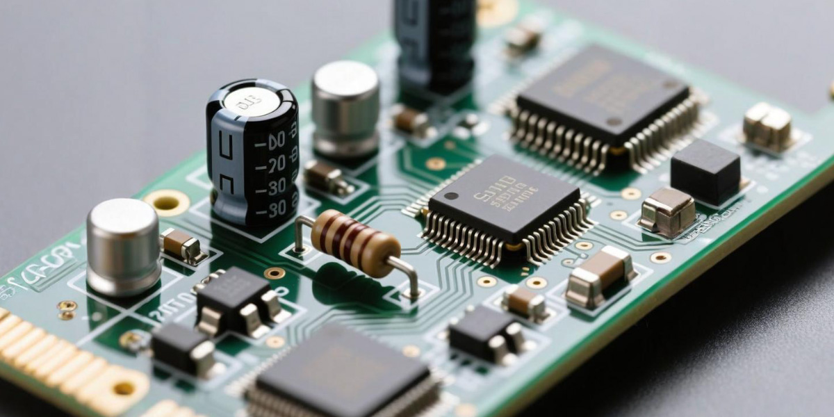
Capacitors look simple on the PCB, but their behavior is complex. Ceramic, electrolytic, film, and polymer types all behave differently with temperature, DC bias, and frequency.
Typical capacitor parameters:
| Parameter | Symbol | Typical Range | Why It Matters |
|---|---|---|---|
| Capacitance | C | pF – mF | Energy storage, filtering strength, timing constants. |
| Voltage Rating | V_rated | 6.3 – 630 V (common ranges) | Max DC/RMS voltage; usually derated (often ≥ 2× application voltage). |
| Tolerance | ±% | ±5%, ±10%, ±20% | Important in timing and precision filter applications. |
| Dielectric / Series | — | X7R, X5R, C0G, electrolytic… | Defines stability vs. temperature, DC bias behavior, and losses. |
| Equivalent Series R | ESR | mΩ – Ω | Affects ripple current, heat, and control loop stability in power supplies. |
| Ripple Current Rating | I_ripple | Application-dependent | Max AC current without overheating. |
| Operating Temperature | T_op | −40 – 105/125 °C (typical) | Life expectancy falls rapidly near the upper limit. |
For high-reliability designs such as chargers, adapters, and LED drivers, common practices include:
Inductors store energy in a magnetic field. In power electronics they set switching ripple, transient response, and efficiency.
Typical inductor parameters:
| Parameter | Symbol | Why It Matters |
|---|---|---|
| Inductance | L | Determines ripple current and energy storage; higher L lowers ripple. |
| Rated Current | I_rated | Current at which temperature rise reaches the specified limit. |
| Saturation Current | I_sat | Current where inductance drops significantly; exceeding it distorts waveforms. |
| DC Resistance | DCR | Defines copper losses (I²R) and impacts efficiency. |
| Self-Resonant Frequency | SRF | Frequency where behavior shifts from inductive to capacitive. |
For DC-DC converters you normally size L, I_sat, and DCR together with your switching frequency and ripple-current targets.
In rectifiers, free-wheel diodes, and protection circuits, you typically focus on:
| Parameter | Symbol | Why It Matters |
|---|---|---|
| Repetitive Peak Reverse Voltage | V_RRM | Max reverse voltage; must exceed worst-case transients with safety margin. |
| Average Forward Current | I_F(AV) | Continuous current capability; derated with temperature. |
| Forward Voltage Drop | V_F | Conduction losses and thermal performance. |
| Reverse Recovery Time | t_rr | Critical in high-frequency switching to minimize losses and EMI. |
| Junction Temperature (max) | T_j(max) | Upper limit of safe operation; drives heatsink and layout requirements. |
Fast and ultra-fast diodes are used in high-frequency SMPS. Schottky diodes are common at lower voltages for their low forward drop and short recovery.
For BJTs, MOSFETs, IGBTs, and other power devices, datasheets usually emphasize:
A sound design always ties these parameters back to ambient temperature, PCB copper area, airflow, and any attached heatsinks.
IC datasheets are often much longer, but the same principles apply. Some of the most important IC-level parameters include:
Reading one good vendor design handbook on how to interpret these specs will significantly improve how you read IC datasheets from any supplier.
Beyond individual components, system-level safety parameters are defined by standards such as IPC-2221 for PCB design and various IEC safety standards for end equipment.
Key concepts:
These parameters connect directly to component ratings. If a resistor, capacitor, or MOSFET runs near its maximum temperature rating, or if the working voltage pushes creepage and clearance limits on the PCB, you may need to change the component, the layout, or the derating strategy.
Practical PCB design guides usually provide tables summarizing recommended creepage and clearance distances versus voltage and pollution degree. Combining those tables with component ratings is the foundation of safe, certifiable hardware.
Even if your design is perfect on paper, production practices can quietly undermine performance:
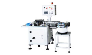
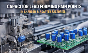
For this reason, many power-electronics, household appliance, and industrial-control manufacturers rely on automated electronic component forming machines (电子元件成型机) in their production lines. Modern resistor lead forming machines and capacitor lead forming machines can:
When design teams and manufacturing engineers review a new product together, it is useful to consider early how leaded components will be processed on electronic component forming machines. That alignment reduces rework, improves first-pass yield, and makes it more likely that real-world parameter behavior matches the calculations made during design.
To turn all of this into a repeatable design habit, you can use a simple checklist whenever you add or change a component in your design:
To go deeper into specific parameter topics, many engineers regularly consult:
When you treat datasheets as the contract between your design and reality — and you align them with robust manufacturing practices and well-tuned electronic component forming machines on the factory floor — you greatly increase the chance that your products will meet specification not only in simulation, but after thousands of hours of real-world use.
Q1: What are the most important electronic component parameters in power electronics?
A1: In power electronics, the most critical parameters usually include voltage and current ratings, power dissipation, temperature limits, ESR for capacitors, RDS(on) for MOSFETs, and creepage and clearance distances on the PCB. These parameters determine efficiency, reliability and safety in real-world operation.
Q2: How do I read a datasheet if I am a beginner?
A2: Start with the first page summary to check if the part fits your application. Then review the absolute maximum ratings, recommended operating conditions and electrical characteristics. Finally, study the graphs to see how parameters change with temperature, frequency and load. Over time you will recognize common patterns across different manufacturers.
Q3: Why are creepage and clearance parameters so important?
A3: Creepage and clearance define the minimum safe distance between conductive parts on a PCB. If these distances are too small for the operating voltage and pollution level, your product may fail safety tests, experience arcing, or suffer from long-term insulation breakdown.
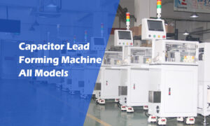
Q4: How can electronic component forming machines improve reliability?
A4: Electronic component forming machines control lead length, angle and spacing with consistent force. This reduces mechanical stress on components, improves solder joint quality and helps real assemblies meet the creepage, clearance and thermal assumptions used in the original design.
Q5: When should I derate electronic component parameters?
A5: You should derate parameters whenever your design operates near a component’s limits or in harsh conditions. Common practices include lowering the allowed power dissipation for resistors, using capacitors at 50–70% of their voltage rating, and adding thermal margin for semiconductors based on real measured temperatures.
When you’re just getting

Choosing the right capaci
A capacitor lead cutter i
Capacitor lead forming ma
Charger and power adapter

If your through-hole (rad