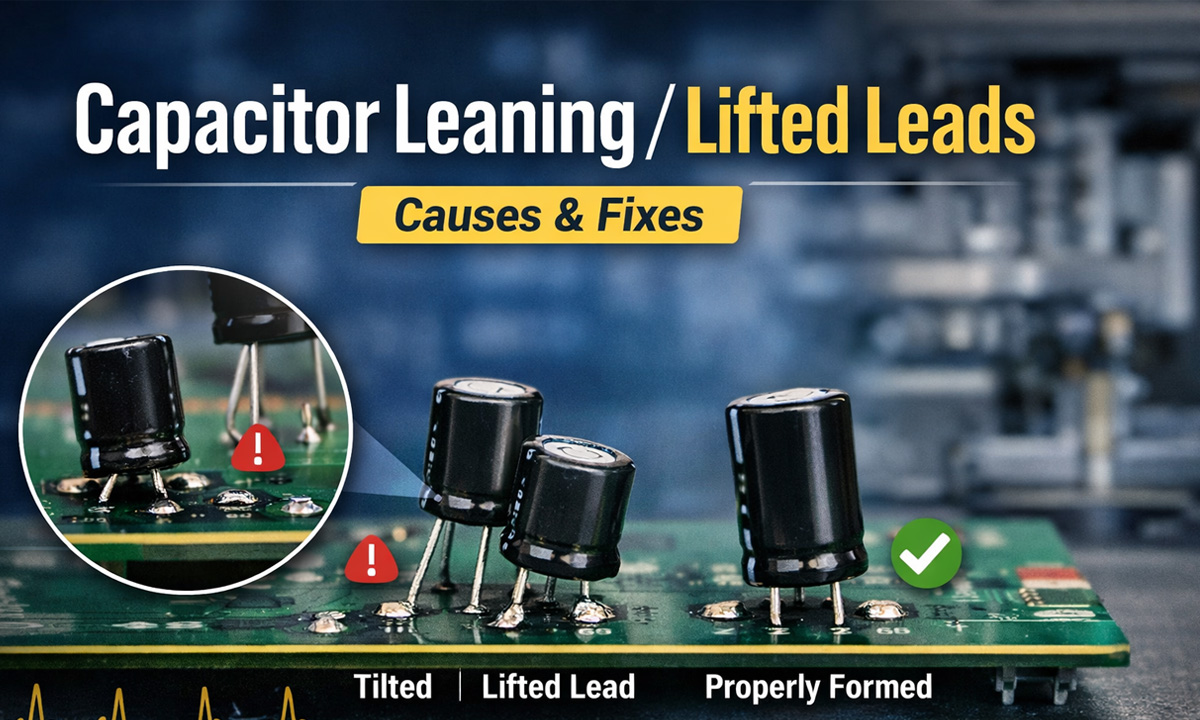
If your through-hole (radial) capacitors don’t sit flat and centered—they lean, rock, or show one leg “floating”—it’s rarely “just cosmetic.” In production, that small geometry error often snowballs into insertion slowdowns, solder defects, clearance violations, and early-life failures.
What “tilt,” “skew,” and “lifted legs” actually mean
In QA terms, you’re typically seeing one or more of these forming outcomes:
- Pitch error: lead spacing doesn’t match the PCB hole spacing → parts won’t drop in cleanly. Nichicon explicitly recommends confirming that capacitor lead spacing matches PCB hole spacing before installation.
- Coplanarity / out-of-plane leads: one lead is higher or twisted → the body rocks and one leg doesn’t fully seat.
- Uneven cut length / clinch geometry: one side is longer or clinched differently → the can leans after insertion/clinching.
Why forming accuracy matters (the “real” problems it causes)
1) Auto-insertion jams + slower takt time
What teams usually observe: when pitch/coplanarity is inconsistent, insertion heads start “fighting” the part. You’ll see:
- higher mis-insert and jam rates
- more manual straightening at the line
- inconsistent seating height (hurts downstream solder/inspection)
Nichicon also cautions that automatic insertion and clinching should not apply excessive force.
2) Through-hole solder defects (wave/selective) and weaker joints
A tilted capacitor often means the lead is not centered in the barrel or not fully seated. That changes wetting dynamics and increases:
- insufficient barrel fill / hole fill variation
- opens / intermittent joints (especially on thick boards or high thermal mass pads)
- fillet shape inconsistency, leading to inspection rejects
IPC J-STD-001 describes the goal of achieving full PTH fill and specifies minimum acceptable conditions for through-hole connections (e.g., vertical fill requirements by class).
3) Clearance violations and rework risk from lead protrusion
Bad forming often causes long protrusion on the solder side. That can violate electrical spacing or interfere with packaging.
J-STD-001E sets explicit protrusion expectations; for supported holes it lists maximum lead protrusion (example: Class 2 max 2.5 mm, Class 3 max 1.5 mm) and warns protrusion should not exceed 2.5 mm if it may violate electrical spacing or risk damage.
4) Hidden mechanical stress that shortens capacitor life
Here’s the E-E-A-T piece most teams miss: mechanical stress on the lead-to-seal interface.
- Panasonic warns to avoid moving the capacitor after soldering to prevent stress where lead wires enter the seal.
- Nichicon warns not to tilt, lay down, or twist the capacitor body after it has been soldered to the PCB.
So if your process “fixes” tilt by pushing caps straight after soldering, you may be trading appearance for long-term reliability.
5) AOI appearance rejects and inconsistent assembly height
Even when electrically acceptable, leaning cans commonly trigger:
- AOI / visual rejects for misalignment
- height/keepout nonconformance (covers, shields, housings)
- creepage/clearance concerns in high-voltage areas
Root causes: where forming accuracy usually goes wrong
Most “tilt/lift” issues trace back to repeatability in four steps:
- Feed & straighten
- lead twist, inconsistent lead set from packaging, or poor straightening
- Cut length control
- blade wear or timing drift → left/right length mismatch
- Forming die geometry
- wrong bend location, inconsistent bend radius, springback variability
- Hold-down & alignment during bend
- insufficient clamping or guide wear → out-of-plane leads
IPC J-STD-001E also defines lead forming expectations such as not damaging seals/welds and minimum straight length before a bend, plus recommended bend radius ranges by lead diameter.
Fast diagnosis: 5 checks that pinpoint the cause
Use these as a “10-minute triage” before you blame the capacitor supplier:
Check 1 — Pitch vs hole spacing (first)
- Compare formed pitch to PCB hole pitch with a simple go/no-go gauge.
- Nichicon explicitly calls out verifying lead spacing matches hole spacing prior to installation.
Check 2 — Coplanarity on a flat reference plate
- Place the formed part on a flat plate: do both leads touch evenly?
- If not: you likely have guide wear, clamping issues, or out-of-plane bending.
Check 3 — Left/right cut length consistency
- If one lead consistently longer: cutter wear, timing, or feed indexing.
Check 4 — Bend location distance from body
- J-STD-001E requires a minimum straight length before the start of the bend radius and provides bend-radius guidance by lead diameter.
- If you bend too close to the body, you increase seal stress risk.
Check 5 — Protrusion after insertion/clinch
- If protrusion is excessive or inconsistent, re-check cut length control and clinch tooling.
- J-STD-001E provides protrusion limits by class (e.g., Class 2 vs Class 3).
Practical fixes that actually hold up in production
Fix A — Control pitch + coplanarity together (not separately)
A common mistake is “dialing pitch” while ignoring out-of-plane error. You need:
- stable guides + consistent clamping during bend
- forming dies designed for the lead diameter and stiffness range you run
Fix B — Treat tooling wear as a “quality input”
If you only inspect the PCB after solder, you’re inspecting too late. Put a simple formed-lead QC gate:
- every X parts (or every reel/box), sample and log pitch/coplanarity/cut length
- swap wear parts on trend, not on failure
Fix C — Stop “after-solder straightening”
It feels like a shortcut, but both Nichicon and Panasonic warn against post-solder bending/moving because it stresses the seal/lead interface.
If you must correct alignment, do it before soldering (and ideally before insertion).
Fix D — Match the machine type to your variability
If your capacitor mix includes different diameters/lead hardness/pitches, you typically need:
- easier repeatable setup (pitch & bend location)
- stable forming accuracy across batches
Use the capacitor lead forming machine buying guide as a spec checklist for accuracy, adjustability, and maintenance points.
And if you’re evaluating solutions now, start with the machine category overview here: capacitor lead forming machine.
Featured Snippet FAQ
Why do through-hole capacitors lean after insertion?
Most leaning comes from pitch mismatch, out-of-plane forming, or uneven lead length, which prevents the capacitor from seating flat and centered. Nichicon recommends confirming lead spacing matches PCB hole spacing before installation.
Can leaning capacitors cause soldering problems?
Yes. Misalignment increases the chance of incomplete barrel fill, poor wetting, and inconsistent fillets. IPC J-STD-001 sets minimum acceptable conditions for through-hole solder connections.
Is “straightening after soldering” safe?
Usually no. Nichicon warns against tilting/twisting after soldering, and Panasonic warns against moving the capacitor after soldering due to stress where leads enter the seal.
How long can the lead protrusion be after soldering?
It depends on class and design, but IPC J-STD-001E provides protrusion limits (e.g., supported holes: Class 2 max 2.5 mm, Class 3 max 1.5 mm) and cautions protrusion should not violate electrical clearance.