
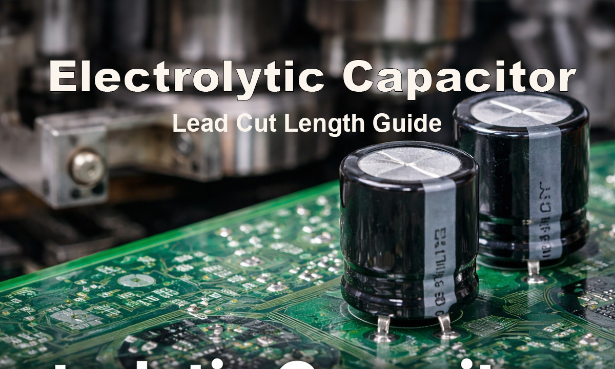
Electrolytic capacitors are still one of the most common through-hole components on power supplies, appliance control boards, industrial controllers, and automotive electronics. Yet many wave-solder defects that look “random” on the line come back to something simple upstream: lead cut length (and the consistency of that cut after forming).
A good lead-length spec is not “as short as possible.” It’s a controlled balance that:
- Inserts smoothly without bending or scraping plated holes
- Produces stable barrel fill and clean fillets in wave soldering
- Avoids solder-side issues like icicles, solder spikes, and bridging
- Improves real-world mechanical reliability under vibration and handling
This guide explains how to set lead cut length the way US manufacturing teams typically think about it—using the terminology your buyers and process engineers will search.
What “lead cut length” actually means in production
Teams often say “lead length,” but wave-solder results track most closely to lead protrusion on the solder side.
In practice you’ll see specs written three different ways:
- Body-to-tip lead length (measured after cutting/forming at the prep station)
- Protrusion past the PCB underside after insertion (pre-wave)
- Final protrusion after soldering and trim (cosmetic/clearance requirement)
For process control, the most useful target is usually:
Protrusion after insertion (before wave solder).
Because that single number strongly influences heat transfer, wetting, and solder drainage behavior during wave.
Why electrolytic capacitor lead length affects wave solder so much
Wave solder is a controlled interaction of heat + flux + solder flow + drainage. Lead length influences all four.
Heat transfer into the plated through-hole
The lead is a heat path into the hole barrel.
- Too short: less heat delivered into the barrel → higher risk of insufficient barrel fill, cold joints, and marginal wetting
- Moderate protrusion: more stable thermal path → more consistent wetting and fill, especially on heavier electrolytics
Solder drainage and bridging risk
The exposed lead below the board changes how solder drains off.
- Too long: increased risk of icicles and solder spikes, and a higher chance of bridging on tighter pitches
- Too short: can reduce wetting margin and make barrel fill more sensitive to small changes in flux and conveyor speed
Clinching changes what “good length” looks like
If you use lead clinching (bending leads on the solder side to hold parts for wave solder), you need enough length to form the clinch without overstressing pads or barrels. Too little lead can cause inconsistent clinches and mechanical stress at the joint.
Leads too short vs too long: the failure patterns
If leads are too short
Common symptoms:
- Incomplete or unstable barrel fill
- Smaller fillets and less consistent wettinge/wetting shape
- Higher risk of opens under vibration on large/heavy capacitors
If leads are too long
Common symptoms:
- More icicles, spikes, and “solder tails”
- More bridging and cleanup work
- Clearance risks and a bigger safety hazard for handling/rework
- Extra trimming steps that add time and variation
A well-chosen protrusion target reduces both sets of problems.
The practical method to set lead cut length (line-ready)
Instead of guessing a body-to-tip length, set your target protrusion first, then back-calculate the cut program.
Step 1: Lock your board and hole conditions
Collect these before finalizing the spec:
- PCB thickness (don’t assume 1.6 mm if you run mixed products)
- Finished hole diameter and lead diameter (fit affects insertion and solder flow)
- Whether you use clinching
- Any required standoff from the board (sometimes used for heat stress or cleaning)
Step 2: Choose the target protrusion (pre-wave)
Most wave solder lines run best with a short, consistent protrusion that supports wetting and barrel fill without creating drainage artifacts. Your final number should be validated on first-article boards and tuned using your defect Pareto (bridging vs fill).
Step 3: Back-calculate the body-to-tip cut length
Use this production-friendly relationship:
Cut Length (body-to-tip) = Seating height + PCB thickness + Target protrusion (+ clinch allowance if used)
The critical detail is seating height. If your forming method changes how the capacitor sits, your correct cut length changes too. That’s why consistent forming is often the bigger lever than trimming alone.
If your process includes automatic forming from bulk radial parts, a dedicated machine like FL-809 is designed for stable forming output and consistent downstream lead length control:
Internal link: FL-809 Automatic Bulk Radial Capacitor Lead Forming Machine
How lead cut length ties to solder-joint strength
For through-hole electrolytics, “solder-joint strength” in the real world usually means resisting:
- Lead pull and pad peel during handling
- Vibration fatigue
- Thermal cycling that creates micro-cracks
Lead cut length affects strength mainly through three mechanisms:
1) Barrel fill consistency
A joint with stable fill and wetting is generally more mechanically robust. Too-short protrusion can make fill more sensitive to small process swings.
2) Fillet geometry repeatability
Strength isn’t just “more solder.” It’s a consistent fillet shape that doesn’t introduce stress risers. A consistent protrusion helps fillet geometry stay consistent across boards.
3) Stress distribution at the lead-to-joint transition
Proper forming (stress relief) plus correct protrusion reduces bending loads at the joint heel. This is especially important on taller capacitors that can act like a small lever under shock/vibration.
Why forming consistency is the hidden requirement
Many factories attempt to “fix” wave solder defects by changing solder parameters first. But if lead prep is inconsistent—especially seating height and lead geometry—wave solder becomes a moving target.
If you’re selecting a forming approach (radial lead forming, kink forming, stand-off styles, etc.), this overview page can help align equipment choice to output requirements:
Internal link: Radial Lead Forming Machines
A copy-paste spec template for your SOP
Use this format to standardize across prep, insertion, and wave solder:
Electrolytic Capacitor Lead Prep Spec (Wave Solder Line)
- Component: Radial electrolytic capacitor (lead dia: ___)
- PCB thickness: ___ mm (___ in)
- Finished hole dia: ___ mm
- Forming style: straight / kinked / stand-off / clinched
- Target protrusion after insertion (pre-wave): ___ mm (___ in)
- Lead cut length (body-to-tip, after forming): ___ mm (___ in)
- Tolerance: ± ___ mm
- Visual checks: no bent leads, no plating scrape marks, defined seating/standoff
- Wave solder focus: stable barrel fill, minimal icicles/bridging, consistent fillets
This keeps everyone aligned on the number that actually matters for wave solder—protrusion—while still providing a measurable cut-length control at the machine.
Quick troubleshooting: what to adjust first
Problem: lots of icicles / solder spikes
What to try:
- Slightly reduce protrusion target (keep it consistent)
- Verify wave setup: conveyor angle, contact time, solder temperature, flux coverage
- Confirm you’re not over-clinching or leaving excessive lead below board
Problem: insufficient barrel fill on larger electrolytics
What to try:
- Ensure protrusion isn’t too short (heat transfer is the limiter)
- Check flux coverage and preheat adequacy
- Confirm pad/hole design supports wetting (thermal relief, copper balance)
Problem: insertion bending / slow insertion / damaged holes
What to try:
- Check lead-to-hole fit
- Improve forming symmetry and seating height consistency
- Then re-tune cut length to hit the protrusion target reliably
Where buyers usually go next
If your team is comparing machine approaches (bulk forming, cutting + forming combinations, throughput tiers, and what to buy for different capacitor types), this buying guide is a good next step:
Internal link: Top 5 Electrolytic Capacitor Lead Cutting & Forming Machines in 2025: A Complete Buying Guide
Final thoughts
Lead cut length is best treated as a process parameter, not a rough operator preference. The most reliable way to spec it is:
- define the target protrusion after insertion,
- make forming output stable (seating height + geometry),
- set the cut program to hit protrusion consistently,
- validate on first-article boards and tune based on wave solder defect data.
When you control lead prep this way, wave solder becomes easier to stabilize, defects drop, and solder-joint strength becomes more repeatable across lots—especially on large electrolytics that see real mechanical stress in the field.