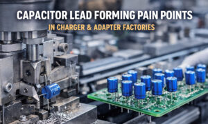
“Capacitor lead forming” sounds like a standardized step—until you run multiple capacitor types on the same line and defects start showing up: insertion jams, tilted parts, cracked leads, seal stress, and solder inconsistencies.
The reality is simple: capacitor construction determines how the leads behave under cutting and bending. If you match the forming setup to the capacitor type, you’ll reduce scrap, stabilize throughput, and avoid downstream soldering and insertion problems.
If you’re comparing equipment for different capacitor families, start with a proper machine overview here:
Capacitor lead forming machine
And if you want a step-by-step buying checklist (lead diameter, pitch tolerance, speed, changeover, etc.), see:
5 Must-Consider Factors When Choosing a Capacitor Lead Forming Machine in 2026
Why “Capacitor Type” Changes the Forming Rules
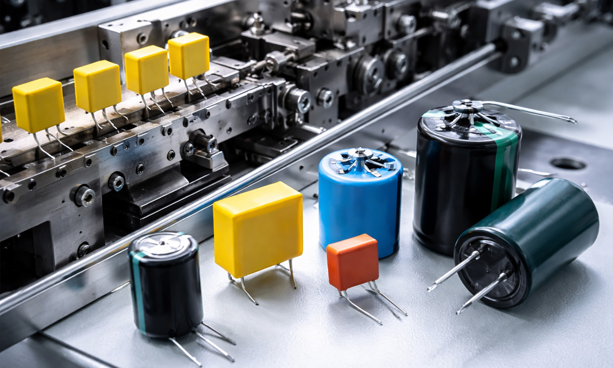
Lead forming isn’t just “cut to length + bend to pitch.” The machine is applying force through metal leads into a body that might be:
- Seal-sensitive (aluminum electrolytics with rubber bungs)
- Brittle (ceramic bodies)
- Epoxy-sealed (film box caps)
- Heavy / thick-leaded (supercapacitors/EDLC)
That changes four things immediately:
- Where you can safely bend (bend point)
- How tight the bend can be (bend radius)
- How consistent pitch must be (PCB fit & insertion)
- How stable feeding and guiding must be (skew, tilt, bounce)
1) Aluminum Electrolytic Capacitors: Protect the Seal Zone
What’s different: radial cans often use a rubber bung/seal area where the leads exit the can. That region is mechanically sensitive.
What to prioritize
- Bend point control: keep bending force away from the seal/bung area.
- Consistent cut length: stabilizes wave solder fillet shape and joint strength.
- Low-scratch guiding: minimize lead scuffing that can hurt solderability.
Shop-floor failure pattern (common scenario)
A line runs fine for a week, then field returns show intermittent failures. When the parts are inspected, the leads were bent too close to the bung. The seal area saw repeated stress, and failures appeared later (not immediately after forming).
How to set it up
- Use a repeatable lead datum (same reference point every time).
- Avoid “over-clamping” that grips the body and transmits force into the seal.
- Verify by doing a short pilot run and checking:
- pitch consistency
- lead length consistency
- any visible seal deformation or lead whitening
2) Film Capacitors (Box-Type): Pitch Accuracy + Body Clearance Matter Most
What’s different: box film capacitors often have epoxy-sealed lead exits and stiffer leads. The body is rectangular, so it interacts with guides differently than a round can.
What to prioritize
- Pitch accuracy (PCB hole alignment is unforgiving).
- Bend radius control (reduce work-hardening and lead cracking).
- Clearance & anti-skew guidance (rectangular bodies can rotate and drift).
Shop-floor failure pattern (common scenario)
Operators report “it inserts fine for one batch, then jams the next.” The root cause often isn’t the PCB—it’s body tolerance + guide mismatch. A guide designed around round electrolytics lets box caps rotate slightly, creating pitch drift and insertion failures.
How to set it up
- Use guides designed for rectangular body stability (anti-rotation).
- Treat pitch as a “critical dimension” and measure it frequently during the first shift after changeover.
3) Ceramic Leaded Capacitors: Handle Like Brittle Components
What’s different: ceramics are physically brittle. Even if the lead bends fine, side loading or impact can chip the body or crack internal structure.
What to prioritize
- Gentle feeding (reduce bouncing/misalignment).
- Stable seating before the cut/bend (no partial engagement).
- Lower vibration at higher speeds.
Shop-floor failure pattern (common scenario)
“Random cracks” appear, but only when speed is increased. The forming tooling didn’t change—what changed was vibration and part bounce. Small ceramics can momentarily lift or mis-seat in the guide, then get side-loaded during bending.
How to set it up
- Stabilize feeding (fixtures/track, controlled entry).
- Increase speed only after confirming seating repeatability.
4) Tantalum (Leaded): Orientation and Body Stress Are the Risk
What’s different: molded/epoxy bodies can crack if clamped incorrectly, and polarity orientation matters for inspection and assembly.
What to prioritize
- Orientation control (polarity marking consistency).
- Avoid body clamping (control by lead datum where possible).
- Minimize torsion on the lead exit area.
Shop-floor failure pattern (common scenario)
AOI flags polarity inconsistently because parts rotate during feeding/forming. The forming dimension is correct, but the line loses time on rework or manual sorting.
How to set it up
- Add orientation-friendly handling (keyed tracks, consistent part presentation).
- Validate polarity marking visibility after forming (don’t assume).
5) Supercapacitors (EDLC): Thick Leads Need Different Force and Radius
What’s different: heavier parts and thicker leads increase forming force, tool wear, and the chance of bending asymmetry if the setup isn’t rigid.
What to prioritize
- Stronger drive and rigid tooling
- Larger bend radii
- Slower, controlled forming (especially during setup)
Shop-floor failure pattern (common scenario)
A factory tries to run thick-lead EDLC parts on a setup tuned for stand
How to set it up
- Treat EDLC as a separate “category” with dedicated tooling.
- Monitor tool wear earlier and more frequently than with small parts.
What Actually Changes on the Forming Machine (By Capacitor Type)
No matter the capacitor family, your setup usually changes in these five areas:
- Lead diameter range & hardness
- Target pitch + tolerance window
- Bend point and bend radius
- Cut length consistency
- Feeding and anti-skew guidance
If you’re selecting equipment based on these variables, use the checklist here:
5 Must-Consider Factors When Choosing a Capacitor Lead Forming Machine in 2026
A Practical “First-Run Validation” Checklist (Use This Every Changeover)
Before you ramp to full speed, validate with a small pilot batch:
- Measure lead pitch (multiple samples across the batch)
- Measure cut length (confirm consistency for soldering/insertion)
- Visual check for:
- lead scratches
- lead whitening (sign of overstress)
- body chips/cracks (ceramics)
- seal deformation risk (electrolytics)
- Try-fit on a PCB or insertion fixture (fast reality check)
- Solder trial if your next step is wave solder (confirm wetting and joint shape)
If you want the machine capabilities that make these checks pass consistently—especially when running mixed capacitor types—start here:
Capacitor lead forming machine
Quick Recommendations for Mixed-Type Production Lines
If your line runs electrolytics + film + ceramics (common in power supply boards), prioritize:
- fast pitch changeovers
- stable datum control
- tooling sets by body geometry (round vs box)
- anti-skew guides
- repeatable feeding
This is where a purpose-built capacitor forming solution typically pays back: fewer insertion stops, fewer solder defects, and less rework time.
FAQ
Can one lead forming setup work for all capacitor types?
A single machine can often run many types, but a single setup usually can’t. Different capacitors typically require tooling + guide + parameter changes to stay stable.
Which capacitor type is most sensitive to forming damage?
Ceramics are most sensitive to impact/side loading. Electrolytics are sensitive around the seal zone. Film caps are sensitive to pitch drift and lead fatigue if bend radius is too tight.
What’s the #1 cause of “can’t insert into PCB holes”?
Most often it’s pitch inconsistency caused by guide mismatch, skew, or wear—especially with box film capacitors and mixed-tol