High-power resistors are core safety and control components in modern power supplies, EV chargers, solar inverters, and battery energy storage systems (BESS). They shape inrush current, dissipate braking energy, discharge dangerous voltages, and provide accurate current sensing. If they are undersized or poorly selected, the result can be overheated boards, nuisance shutdowns, or even catastrophic failures.
This article explains what qualifies as a high-power resistor, how the main technologies compare, and how to size and select devices for power and new energy applications using data-driven examples and tables.
If you’re not fully confident with basic resistor specs and terminology yet, it’s worth reviewing our broader Electronic Component Parameter Guide first, then coming back to the high-power specifics below.
1. What Do We Mean by “High-Power Resistor”?
There’s no universal threshold, but in practical design:
- Low-power resistors: 1/16 W to 1 W (typical SMD and small through-hole).
- High-power resistors: roughly ≥ 2 W, up to hundreds of watts per device or kilowatts for resistor banks/braking grids.
They are designed for:
- Continuous dissipation of large power
- Short, high-energy pulses (inrush, braking, crowbar events)
- Robust mechanical and thermal paths
- Operation in harsh environments (e.g., EV, industrial, outdoor)
1.1 Main technology options
| Technology | Typical Single-Resistor Power | Typical Resistance Range | Key Advantages | Limitations / Notes |
|---|---|---|---|---|
| Wirewound (axial, cement, housed) | 2–200 W | 0.1 Ω – 100 kΩ+ | High power, robust, excellent surge handling | Inductive unless wound specially |
| Metal oxide / metal film (power) | 2–20 W | 10 Ω – 1 MΩ+ | Better stability, non-flammable options | Lower surge capability than heavy wirewound |
| Thick-film power (SMD, modules) | 1–50 W | mΩ – MΩ | Compact, non-inductive, good for sensing | Thermal design is critical |
| Current sense shunts / metal plate | 1–100 W+ | 0.1 mΩ – 100 mΩ | Very low R, good accuracy, Kelvin connection | Needs careful layout and cooling |
| Braking grids / resistor banks | 100 W – kW+ | 1 Ω – 1 kΩ | Handles huge braking/dump energy | Bulky, needs ventilation or forced air |
2. Key Parameters That Matter in High-Power Designs
Choosing a high-power resistor is not just “ohms and watts.” You need a full view of electrical, thermal, and reliability parameters.
2.1 Power rating and derating
Datasheet power rating Pᵣ is specified under defined conditions (ambient temperature, mounting, airflow). Real use must respect derating curves:
- At 25 °C: device can usually handle 100% of Pᵣ
- At 70 °C or higher: allowed power may drop linearly to 0 at 155–200 °C
Basic starting rule:
Continuous power: Pᵣ ≥ 2 × P_calculated
Harsh environments (EV, outdoor, sealed enclosures): 3–4 × margin is often safer
Where:
P_calculated = I² × R = V² / R
Example – Bleeder resistor in a 400 V DC bus
- Target continuous dissipation: 4 W
- With 2× margin → pick at least an 8 W type
- With 3× margin in a hot sealed enclosure → pick ~12 W type
2.2 Resistance, tolerance, and TCR
For many high-power roles (braking, discharge), absolute accuracy is less critical:
- Tolerance: ±5% or ±10% is often acceptable
- Temperature coefficient of resistance (TCR): 50–300 ppm/°C
For current sensing or calibrated power monitoring, accuracy is crucial:
- Tolerance: ±1% or better, sometimes down to ±0.1%
- TCR: 50 ppm/°C or lower helps keep readings stable over temperature
2.3 Pulse and surge capability
High-power resistors often see short, intense pulses:
- Inrush current at startup
- Dynamic braking events
- Short-circuit crowbar or fault dumps
Datasheets therefore specify:
- Short-time overload (e.g., 10× Pᵣ for 5 seconds)
- Single-pulse and repetitive-pulse capability curves
Ignoring these curves is one of the most common causes of unexpected resistor failures.
2.4 Thermal resistance and mounting
Thermal performance is defined by:
- Rθ (thermal resistance) from resistor to ambient or to heatsink
- Mounting style: metal housing bolted to heatsink, ceramic exposed to airflow, resistor grids in ventilated enclosures
- Interface quality: torque, flatness, and thermal compound where needed
A resistor might meet electrical specs but fail thermally if it’s mounted to a small, poorly cooled plate or inside a hot, sealed box.
2.5 Comparative parameter snapshot
The table below summarizes typical numbers for representative high-power types (values are indicative, not tied to a specific brand):
| Parameter | Wirewound Cement 50 W | Metal-Housed 100 W | Thick-Film Power SMD 5 W | Shunt Plate 10 W |
|---|---|---|---|---|
| Typical Resistance Range | 1–1 kΩ | 1–10 kΩ | 10 mΩ – 1 MΩ | 0.5–50 mΩ |
| Tolerance | ±5–10% | ±5% | ±1–5% | ±0.5–1% (precise) |
| TCR (ppm/°C) | 50–200 | 50–200 | 50–300 | 50–100 |
| Surge / Pulse Capability | Very good | Very good | Good (needs checking) | Good (depends on R) |
| Inductance | Moderate to high | Moderate | Low | Very low |
| Mounting | PCB / chassis | To heatsink | PCB | PCB / busbar |
3. High-Power Resistors in Power Supplies
In AC-DC and DC-DC power supplies (chargers, adapters, industrial SMPS), high-power resistors appear in several key functions.
3.1 Inrush current limiting / pre-charge
Bulk capacitors on the DC bus can draw very high inrush currents when first energized. A series resistor:
- Limits inrush to safe levels
- Protects rectifiers, PFC stages, and capacitors
- Often gets bypassed by a relay/triac after startup
Design example – Pre-charge of 400 V DC bus
- DC bus: 400 V
- Total capacitance: 470 μF
- Desired inrush limit: 10 A
Approximate initial R_precharge:
R ≈ V / I = 400 / 10 = 40 Ω
At turn-on:
P_initial = V² / R = 400² / 40 = 4,000 W (short pulse)
Continuous dissipation afterward is much lower, because the resistor is bypassed. You choose:
- A wirewound 50 W or 100 W metal-housed resistor
- Verify in the datasheet pulse curves that a 4 kW pulse of your duration (e.g., tens of ms) is within safe limits.
3.2 Bleeder and discharge resistors
Bleeder resistors discharge high-voltage capacitors after power-off:
- Improves user and service safety
- Helps comply with safety standards (e.g., discharge below 60 V within a defined time)
Example – Sizing a 400 V bus bleeder
- DC bus: 400 V
- Capacitance: 220 μF
- Target: drop to 60 V in 60 s
Capacitor discharge follows:
V(t) = V₀ · e^(−t / (R·C))
Rearrange for R to meet the target; then calculate continuous power at 400 V:
P_bleeder ≈ V² / R
Results typically lead to:
- R in the 100 kΩ – 470 kΩ range
- Power somewhere between 2–10 W (continuous)
3.3 Snubber and damping networks
In flyback, forward, PFC, and other topologies:
- RC snubbers clamp voltage spikes and damp ringing
- Damping networks around transformers/filters control overshoot
Here you need:
- Moderate power (1–5 W)
- Excellent pulse handling
- Non-inductive resistors to avoid distorting switching waveforms
3.4 Current sensing in power supplies
Low-ohm resistors measure current in:
- PFC stages
- Primary switch current sense
- Output current feedback loops
Requirements:
- Low resistance (mΩ to <1 Ω)
- Tight tolerance (±1% or better)
- Low TCR (50–100 ppm/°C)
These are typically metal plate shunts or thick-film power SMDs.
3.5 Power supply application summary table
| Use Case | Typical Voltage Level | R Range | Power Range (Single) | Main Requirements |
|---|---|---|---|---|
| Inrush / pre-charge | 200–400 V DC | 20–100 Ω | 25–200 W (pulse) | Strong pulse rating, wirewound or housed |
| Bleeder / discharge | 200–800 V DC | 100 kΩ – 1 MΩ | 2–10 W (continuous) | Long-term stability, safety compliance |
| Snubber / damping | Switching node | 10–1,000 Ω | 1–5 W (pulse) | Non-inductive, high pulse life |
| Current sensing | 5–60 V DC rails | 0.5–100 mΩ | 1–10 W | Low TCR, accurate, low inductance |
4. High-Power Resistors in New Energy Systems
4. High-Power Resistors in New Energy Systems
In EV charging, BESS, wind power, and PV inverters, high-power resistors deal with much higher energy and safety demands.
4.1 EV chargers (AC and DC fast charging)
Typical roles:
- Pre-charge of large HV DC link capacitors
- Bleeder resistors for safe discharge after disconnect
- Dump loads or protective loads in fault conditions
Indicative values:
| EV Charger Stage | Voltage Range | R Range | Power Level (Single / Bank) |
|---|---|---|---|
| DC link pre-charge | 400–1,000 V | 50–200 Ω | 50–200 W (pulse, repetitive) |
| HV bleeder / discharge | 400–1,000 V | 100–330 kΩ | 10–50 W (continuous) |
| Fault dump / crowbar (where used) | 400–1,000 V | 5–100 Ω (bank) | kW level for short durations |
4.2 Battery energy storage systems (BESS)
In BESS, high-power resistors are used for:
- Pre-charge of inverter DC link
- Module discharge / maintenance
- Emergency dump loads when disconnecting from grid
Typical design ranges:
- DC bus: 600–1,500 V
- Dump load resistors: 10–200 Ω in banks up to tens of kW
- Discharge resistors: 100–470 kΩ, 10–50 W continuous
4.3 Wind turbines and dynamic braking
When turbines or large drives brake:
- The generator outputs energy that cannot always be pushed back into the grid.
- Braking resistor banks convert this energy into heat.
Typical characteristics:
- System voltages: 400–1,500 V AC/DC
- Resistors: 1–100 Ω in large stainless steel / grid assemblies
- Power: 10–100 kW or more per bank, often in dedicated enclosures
4.4 PV inverters and grid-tied converters
In PV systems:
- High-power resistors handle DC link pre-charge and discharge, similar to EV chargers.
- They may also appear in filter damping networks or special protection circuits.
4.5 New energy application overview
| System Type | Primary Resistor Roles | Typical Voltage Level | Design Focus |
|---|---|---|---|
| EV chargers | Pre-charge, bleeder, dump loads | 400–1,000 V DC | Pulse energy, safety, lifetime |
| BESS | Pre-charge, discharge, dump load | 600–1,500 V DC | Energy handling, maintenance safety |
| Wind turbines | Dynamic braking banks | 400–1,500 V AC/DC | kW-level dissipation, cooling |
| PV inverters | Pre-charge, bleeder, damping | 400–1,000 V DC | Reliability in outdoor conditions |
5. Selection and Sizing Workflow (Power & New Energy)
A disciplined workflow helps avoid under-designed parts:
Step 1 – Define the function and duty cycle
- Inrush limiting, braking, sensing, discharge, damping, dump load?
- Continuous or intermittent? How many events per hour/day?
- Worst-case line conditions and fault scenarios?
Step 2 – Calculate electrical stress
- Use worst-case voltage, current, and duration.
- Compute continuous power and pulse energy (E = P × t or ∫v·i dt for complex pulses).
- Compare with datasheet continuous rating and pulse curves.
Step 3 – Choose technology & package
- Wirewound / metal-housed for high surge and dump loads
- Thick-film / shunts for precise, low-ohm sensing and non-inductive behavior
- Braking grids for kW-level dynamic braking
Step 4 – Verify thermal design
- Model or estimate resistor surface temperature at full load.
- Consider enclosure temperature, airflow, heatsink size, and mounting torque.
- Apply an appropriate derating margin, especially for +60–80 °C ambient.
Step 5 – Consider standards and safety
- Ensure voltage rating, creepage, and clearances meet relevant standards (UL, IEC, automotive).
- Respect coordination with insulation system and protective devices (fuses, breakers, contactors).
Step 6 – Align with procurement and supplier evaluation
- Define acceptable brands and equivalent parts.
- Include resistor pulse/thermal requirements in your supplier evaluation checklists, not just in BOM notes.
- Cross-check that incoming parts match specified technology and ratings—critical for high-risk positions.
6. Manufacturing and Assembly Considerations
High-power resistors are often large, heavy parts with leads or terminals. Poor handling can damage them before they ever reach the field.
Key points:
- Lead forming stress: manually bending thick leads close to the body can crack the coating or stress the internal welds.
- PCB mounting: heavy resistors should often be raised off the board or mechanically supported to handle vibration and thermal expansion.
- Repeatability: in volume production, consistent lead length, pitch, and height above the PCB improves cooling and solder quality.
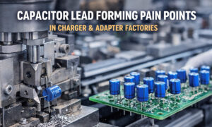
For through-hole power resistors, many factories use dedicated resistor lead forming machines to:
- Control bending radius and keep stress away from the component body
- Standardize pin height for airflow and creepage distance
- Improve wave-solder consistency and reduce manual rework
Good mechanical practice reduces hidden failure modes such as micro-cracks, solder fatigue, or vibration-induced opens—especially important in EV chargers, wind power, and industrial inverters that run for thousands of hours.
7. Common Design Mistakes (and How to Avoid Them)
- Sizing only for average power, ignoring pulses
- Fix: always check pulse overload graphs and add margin.
- Underestimating internal ambient temperature
- The inside of an EV charger or inverter cabinet may sit at 60–80 °C.
- Fix: derate based on realistic enclosure temperature, not room temperature.
- Using inductive wirewound parts in high-frequency positions
- Fix: choose non-inductive types for snubbers and fast switching nodes.
- Ignoring long-term drift and load life
- In BESS or PV, systems run 24/7 for years.
- Fix: check load-life drift specs (1,000–10,000 h) and choose accordingly.
- Treating mechanical handling as an afterthought
- Fix: specify proper forming, mounting, and support in your assembly process, not just in the schematic.
8. Conclusion
High-power resistors are foundational to power electronics and new energy systems. They shape the way energy flows and dissipates under normal operation and during extreme events. Getting them right requires more than picking an ohmic value—you must consider power, pulse energy, TCR, thermal path, mechanical handling, and safety standards together.
By using data-driven calculations, checking real pulse curves, and integrating resistor decisions into your broader component and procurement strategy, you can significantly improve the reliability and safety of your power supplies, EV chargers, PV inverters, and energy storage systems for the long term.