When people ask what “shapes” an LED component lead forming machine can make, they usually mean:
- What lead geometries can it form consistently at production speed?
- Can one machine cover multiple LED/axial parts, or do I need different tooling?
If you’re evaluating machine capability for DIP LEDs and other axial-lead components, start with this product category page: Axial Lead Forming Machines.
What Is an LED Lead Forming Machine?
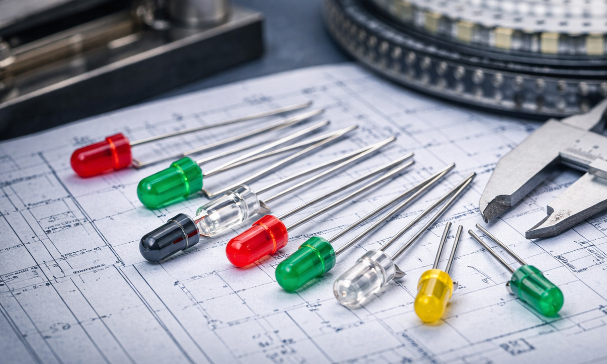
An LED lead forming machine (often used for DIP LEDs and similar axial-lead components) is a production machine that cuts and bends component leads into a required geometry—so the part matches PCB hole pitch, insertion method, and soldering process.
Depending on configuration, it may include:
- Lead straightening (if needed)
- Precise cut-to-length
- One or multiple bend stations
- Optional counting, batching, and jam detection
Why Do Lead Shapes Matter in LED Production?
Because lead geometry directly impacts:
- Insertion success rate (manual, jig-assisted, or automatic insertion)
- Solder quality (lead length and wetting window)
- Consistency and yield (pitch/length deviation causes rework or scrap)
- Reliability (too-small bend radius or excessive stress can damage plating or weaken leads)
In short: the “right shape” reduces downtime, rework, and hidden labor costs.
The Most Common Shapes One LED Lead Forming Machine Can Make
Below are the lead forms most factories request for DIP LEDs. The exact feasibility depends on machine design, tooling, and your tolerance.
1) Straight Cut (Cut-to-Length)
What it is: No bend—just consistent lead length.
Why it’s used: For specific assembly jigs, secondary operations, or custom insertion steps.
Key specs to define: Final lead length, length tolerance, cut quality (burr control).
2) Single 90° Bend (L-Form)
What it is: One right-angle bend at a defined distance from the LED body.
Why it’s used: Simple PCB layouts, clearance constraints, and stable seating height.
Key specs: Bend location, bend angle tolerance, minimum bend radius.
3) Double 90° Bend (Z-Form / Offset Form)
What it is: Two bends creating an offset, often for clearance or height control.
Why it’s used: When the LED body must sit at a specific height or avoid nearby components.
Key specs: Offset distance, parallelism, repeatability at speed.
4) U-Form (Staple / “U” Shape)
What it is: Two parallel legs with a U bridge (or U-like geometry), matching hole pitch.
Why it’s used: Very common for consistent hole pitch insertion and neat assembly.
Key specs: Final pitch, leg length, symmetry, bend radius.
Many buyers shop for “U-form” capability under axial lead forming platforms. See options here: Axial Lead Forming Machines.
5) “Stand-Off” Form (Raised Body / Seating Height Control)
What it is: A bend geometry designed to keep the LED body slightly elevated above the PCB.
Why it’s used: Helps with heat, cleaning, coating, or mechanical clearance.
Key specs: Stand-off height, pitch, and how the form controls body seating position.
6) Kink / Stress-Relief Form
What it is: A small controlled “kink” that acts as strain relief before final insertion geometry.
Why it’s used: Reduces stress transfer to the LED body and improves vibration tolerance.
Key specs: Kink position, angle, and whether it affects insertion alignment.
7) Custom Pitch + Custom Length (Defined by Your PCB Drawing)
What it is: Any non-standard combination of pitch, length, bend positions, and angles.
Why it’s used: Custom LED fixtures, unique PCB constraints, or legacy product requirements.
Key specs: Provide a dimensioned drawing with tolerances and sample parts.
Can One Machine Do Multiple Shapes?
Yes—if the machine supports change tooling and your production plan tolerates changeover time.
In practice, multi-shape capability depends on:
- How many forming stations are built in
- Whether tooling is quick-change
- Whether pitch and bend positions are adjustable with repeatable settings
- Your required tolerance at your target speed
If you run many SKUs, prioritize: changeover design + repeatability over “maximum speed on paper.”
What You Must Specify to Confirm Shape Capability (RFQ Mini-Checklist)
To avoid vague promises and mismatched quotes, include:
- Component type: DIP LED / axial lead component
- Lead diameter range
- Required final pitch
- Required final lead length (after cut)
- Bend angles and bend locations
- Tolerance requirements (pitch/length/angle)
- Target throughput (pcs/hour)
- Feeding method (manual/tube/magazine, etc.)
- Any special requirements (stand-off height, stress relief, burr limits)
Recommended Machine Category for DIP LED Lead Forms
For DIP LEDs and many axial-lead shapes listed above, the most relevant category is:
Axial Lead Forming Machines
That page is also the best internal link target for buyers who are actively comparing solutions.
FAQ
What’s the most common LED lead form for PCB insertion?
U-form and defined-pitch forms are very common because they align directly to PCB hole spacing and improve insertion consistency.
Will tight tolerances limit which shapes I can run fast?
Often, yes. As speed increases, maintaining tight pitch/length tolerances requires better rigidity, guides, and tooling design.
Do different LED lead materials affect forming shapes?
Yes—lead hardness and plating influence springback, bend radius limits, and cut edge quality.