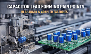
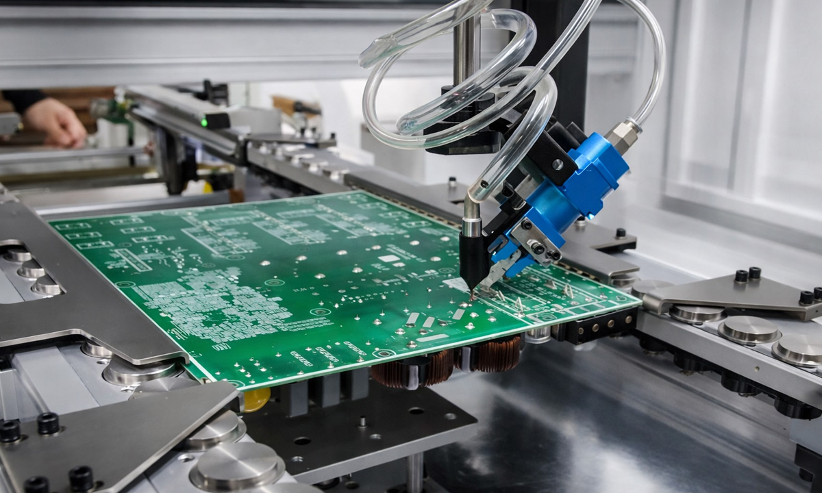
In through-hole (THT) and mixed-technology PCB assembly, lead cutting and forming is one of those “small steps” that quietly determines the final yield. Whether you’re processing resistors, radial electrolytic capacitors, diodes, LEDs, or power packages like TO-220/TO-247, consistent lead geometry directly affects insertion stability, solder joint quality, creepage/clearance, mechanical stress, and long-term reliability.
This guide breaks down what PCB lead cutting & forming is, why it matters, the main forming types, typical components, machine categories (manual / semi-auto / automatic), common problems and their quality impact, and a practical equipment selection framework for engineers and buyers.
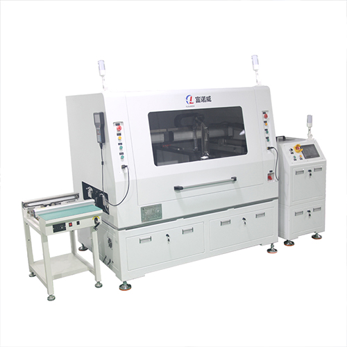
What Is PCB Lead Cutting & Forming?
PCB lead cutting & forming refers to the process of trimming component leads to a defined length and shaping them into the geometry required for PCB insertion or mounting.
It typically includes one or more of the following steps:
- Lead cutting: trimming leads to a target length (e.g., after forming or before insertion)
- Lead straightening: removing shipping bends, improving insertion consistency
- Lead spacing (pitch) setting: matching PCB hole pitch
- Lead bending: creating a specific bend angle and bend radius
- Kink / jog / offset forming: adding a controlled offset for standoff or stress relief
- Stand-off forming: maintaining a designed gap between component body and PCB
- Clinching / retention forming: improving retention before soldering (in some workflows)
The goal is to produce repeatable lead geometry that aligns with PCB design requirements and assembly method (manual insertion, auto insertion, wave soldering, selective soldering, etc.).
Why Lead Forming Matters for PCB Assembly
Lead geometry affects far more than “fit.” In production, lead cutting and forming influences:
1) Insertion success and cycle time
- Correct pitch + consistent lead straightness = fewer jams and less rework
- For auto insertion, small deviations can create repeated stoppages
2) Solder joint quality and reliability
- Consistent protrusion length and lead angle improve solder fillet formation
- Overly short leads can weaken joints; overly long leads can cause bridging or poor fillet shape
3) Mechanical stress and component damage
- Incorrect bend radius or excessive forming force can crack plating, create micro-fractures, or stress the seal on diodes/caps
- Sensitive parts (glass diodes, some LEDs, film capacitors) can be easily damaged without controlled tooling
4) Creepage/clearance and safety compliance
- Especially in power supplies, inverters, and industrial designs
- Lead placement errors can violate spacing rules and trigger compliance issues
5) Yield and long-term field performance
- Poor forming increases latent defects (cracks, stress, loose joints) that show up after thermal cycling or vibration
In short: lead forming is a quality gate. You can have excellent PCB design and soldering, but inconsistent lead prep will still reduce yield.
Main Forming Types (Cut / Bend / Kink / Stand-Off)
Different assemblies require different lead shapes. The most common forming types include:
1) Cut (Lead Trimming)
Purpose: Set final lead length and improve consistency.
Common targets:
- Uniform protrusion for wave soldering
- Clearance management in high-density assemblies
- Cosmetic or safety requirements
Key control points:
- Cut length tolerance
- Burr control (burrs can cause shorts or poor solder wetting)
- Blade wear monitoring
2) Bend (Right-angle / L-form / U-form)
Purpose: Match PCB footprint or mechanical layout.
Typical bend styles:
- 90° bend for mounting or routing
- L-form for insertion profiles
- U-form for specific retention or packaging
Key control points:
- Bend angle tolerance (e.g., ±1–2° depending on application)
- Bend radius (avoid micro-cracks and stress)
- Bend position relative to component body (avoid damaging seals)
3) Kink / Jog / Offset Forming
Purpose: Add an offset section that can:
- Provide stress relief
- Maintain stand-off
- Improve insertion alignment
- Reduce stress transferred to solder joint
This is widely used when you need controlled mechanical compliance (vibration, thermal expansion, or wave-solder flow needs).
Key control points:
- Offset distance
- Offset position
- Lead parallelism after forming
4) Stand-Off Forming
Purpose: Maintain a defined gap between component body and PCB surface.
Why it matters:
- Improves solderability and cleaning
- Helps thermal management (airflow gap)
- Protects components from flux residues and PCB surface stress
Key control points:
- Stand-off height uniformity
- Body-to-bend distance
- Avoiding body contact / scratching
Typical Components Processed by Lead Cutting & Forming Machines
A good electronic component lead forming setup should handle your dominant BOM types and package constraints.
Through-hole passive components
- Resistors (axial): common for cut + kink + pitch adjustment
- Radial capacitors: pitch forming + lead trimming; stability is critical to avoid tilt
- Axial capacitors: similar to axial resistor, but often with different lead stiffness and body fragility
- Film capacitors: can require gentler forming, controlled radius
Discrete semiconductors
- Diodes: glass or epoxy bodies may require strict stress control
- LEDs (THT): optical parts often need stand-off control and lead length consistency
Power packages
- TO-220 / TO-247 / similar: thicker leads, higher force, higher wear; forming must avoid cracking plating or deforming lead width
- Power modules / special packages: often require custom tooling
Practical note: Component lead material (tinned copper, steel core, plated alloys) and lead diameter dramatically change forming force, tooling wear, and achievable tolerance. Always match equipment capability to lead diameter and hardness.
Manual vs Semi-Auto vs Automatic Machines
When selecting a pcb lead forming machine or pcb lead cutting equipment, the biggest decision is the automation level.
1) Manual Machines
Best for:
- Low volume
- Prototyping
- R&D labs and small batches
- High-mix, low-repeat work
Pros:
- Low cost
- Simple operation
- Quick to start
Cons:
- Operator variability affects tolerance
- Lower throughput
- Higher fatigue and inconsistency over long runs
2) Semi-Automatic Machines
Best for:
- Medium volume production
- Multiple SKUs with repeat orders
- Plants that need stable output without full automation investment
Pros:
- Better consistency than manual
- Improved throughput
- Often adjustable via mechanical settings (pitch/length)
Cons:
- Still relies on manual feeding or partial handling
- Setup time matters if SKU changes are frequent
3) Automatic / Fully Automatic Machines
Best for:
- High volume
- Standardized products
- Tight tolerances and high yield requirements
- Integration with upstream/downstream processes
Pros:
- Highest consistency
- High throughput (stable takt time)
- Lower labor cost per unit and fewer human errors
Cons:
- Higher initial investment
- Needs stable component supply and standardized process windows
- Tooling and maintenance become more critical
Process Parameters That Determine Quality
Regardless of machine type, lead forming quality is controlled by measurable parameters. These are the ones that usually decide pass/fail:
1) Pitch (Lead Spacing)
- Must match PCB hole pitch
- Tolerance depends on insertion method (auto insertion usually stricter)
- Monitor: pitch drift from tooling wear or misalignment
2) Lead Length (Cut Length / Protrusion Length)
- Too short: weak solder joints / poor retention
- Too long: bridging risk / collision / cosmetic issues
- Monitor: blade wear, component position repeatability
3) Bend Radius
- Too small: micro-cracking, plating damage
- Too large: fitment issues, geometry interference
- Monitor: die radius wear and material variability
4) Bend Position (Distance to Body)
- Critical for diodes/caps/LEDs where body seals are sensitive
- Monitor: fixture reference stability
5) Lead Straightness and Parallelism
- Impacts insertion success
- Monitor: guide alignment, feeding stability
Common Problems & Quality Impact
Below are the frequent failure modes seen in lead cutting and forming—and why they matter.
Problem 1: Lead cracks or plating fractures after forming
Symptoms: hairline cracks, poor solder wetting, early failure after thermal cycling
Common causes: bend radius too tight, excessive forming force, poor die condition
Impact: latent reliability issues (worst kind)
Problem 2: Burrs after cutting
Symptoms: sharp edges, inconsistent solder, possible shorts
Common causes: worn blade, incorrect blade angle, material hardness mismatch
Impact: solder quality problems, safety concerns, rework
Problem 3: Pitch inconsistency
Symptoms: insertion difficulty, bent leads during insertion, machine jams
Common causes: tooling looseness, guide wear, inconsistent part positioning
Impact: yield drop, downtime, throughput reduction
Problem 4: Lead length variation
Symptoms: uneven protrusion; wave solder bridging or weak fillets
Common causes: unstable component stop position, blade wear, operator variability
Impact: solder defects, rework, cosmetic defects
Problem 5: Component body damage
Symptoms: cracked diode glass, capacitor seal stress, LED lens stress
Common causes: forming too close to body, no stress relief support, wrong fixtures
Impact: immediate scrap or latent failures
Equipment Selection Overview (How to Choose the Right Machine)
Here is a practical framework to choose the right lead cutting and forming equipment.
Step 1: Define your component and geometry requirements
Create a simple “process input sheet”:
- Component type (resistor/cap/diode/LED/TO-220…)
- Lead diameter and material hardness
- Target pitch, lead length, bend type
- Required tolerance level (auto insertion? safety compliance?)
Step 2: Match throughput to automation level
- Prototype/low volume → Manual
- Medium volume/multi-SKU → Semi-auto
- High volume/stable SKU → Automatic
Step 3: Evaluate tooling flexibility and changeover time
For high-mix production, changeover efficiency is often more important than max speed.
Ask:
- How long is changeover (minutes vs hours)?
- Is tooling modular?
- Can operators repeat settings reliably?
Step 4: Confirm process stability and maintenance plan
Tooling wear is inevitable. What matters is predictability.
- Blade replacement frequency
- Die wear monitoring
- Alignment calibration method
- Spare parts availability
Step 5: Consider future expansion and integration
If you expect growth:
- Inline options
- Compatibility with insertion systems
- Data/quality tracking (even simple counters and maintenance logs help)
Quick Comparison Table (Buyer-Friendly)
| Requirement | Best Fit |
|---|---|
| Prototyping / low volume / frequent shape changes | Manual forming/cutting |
| Medium volume / repeated SKUs / moderate tolerance | Semi-auto |
| High volume / strict consistency / auto insertion | Automatic |
| Sensitive components (glass diodes, fragile seals) | Controlled radius + proper support tooling |
| Thick leads (TO-220/TO-247) | Higher-force design + durable tooling |
FAQ: PCB Lead Cutting & Forming Machines
1) What tolerance should a PCB lead forming process target?
It depends on insertion method and hole design. Auto insertion requires tighter repeatability than manual insertion. The safest approach is to set tolerance based on your PCB hole size, lead diameter, and insertion equipment capability.
2) Can one machine handle resistors, capacitors, diodes, LEDs, and TO-220 parts?
Sometimes, but not always efficiently. Wide component variety often requires different tooling sets or even dedicated machines for high-volume lines. A “one-size-fits-all” setup may increase changeover time and reduce precision.
3) What causes lead cracking after forming?
Most often: bend radius too small, forming too close to component body, or excessive force due to material hardness mismatch or worn tooling.
4) How often should blades and dies be replaced?
There’s no universal schedule—material hardness, lead diameter, speed, and maintenance practices all matter. A good plan is to track wear by output count and defect rate trend rather than waiting for failure.
Final Takeaway
A pcb lead cutting equipment or pcb lead forming machine isn’t just a convenience tool—it’s a yield and reliability lever. The best-performing setups focus on:
- Controlled geometry (pitch, length, radius)
- Stable referencing (component positioning)
- Tooling wear management
- Matching automation level to product mix and throughput