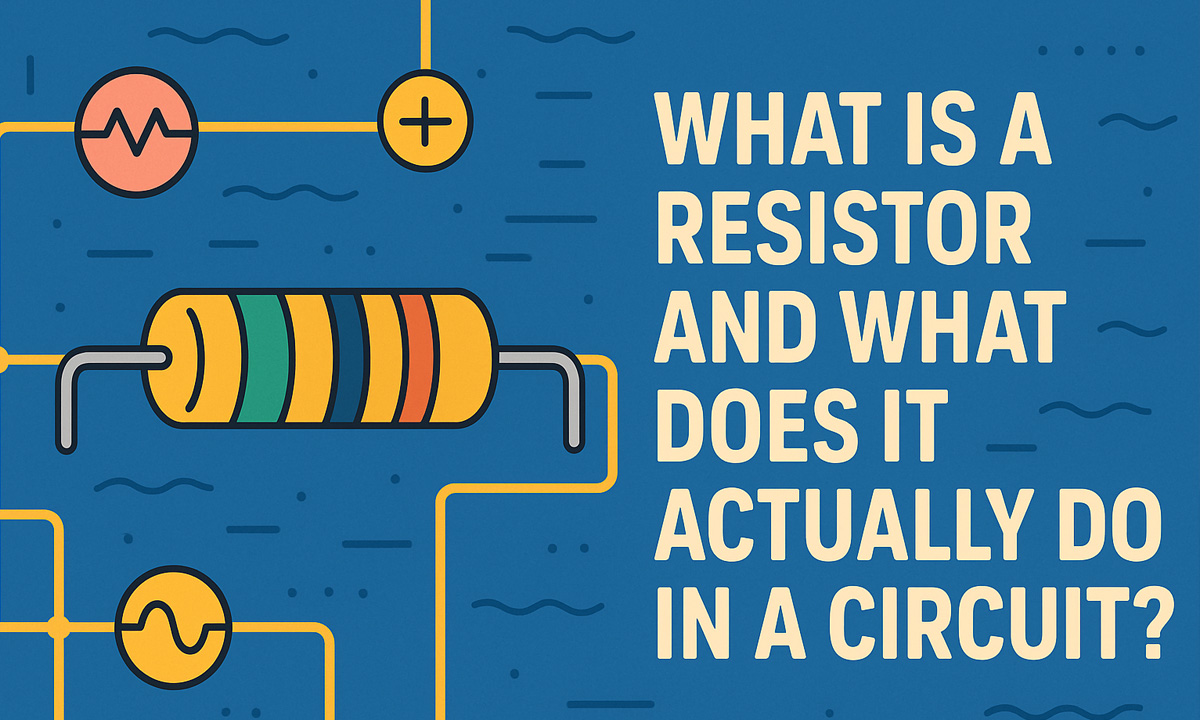
If you open any circuit board—from a phone charger to an industrial power supply—you’ll see dozens or hundreds of tiny parts labeled with “R” on the silkscreen. Those are resistors. They look simple, but they’re doing a lot of quiet work to keep the circuit safe, stable, and accurate.
So what exactly is a resistor, and what does it really do in a circuit?
Basic Idea: A Controlled “Friction” for Current
Electrically, a resistor is a component that opposes the flow of electric current. Its resistance is measured in ohms (Ω). The higher the resistance, the harder it is for current to pass.
The behavior of a resistor is described by Ohm’s law:
- V = I × R
- V: voltage (volts)
- I: current (amps)
- R: resistance (ohms)
This simple relationship is the reason resistors are everywhere. By choosing a specific resistance value, you can control the current in a branch of the circuit or create a specific voltage at a node.
How Resistors Control Current and Voltage
In most circuits, a resistor isn’t just “sitting there” randomly. It’s usually doing one of a few core jobs.
1. Limiting current
One of the most common roles is as a current-limiting resistor. For example, an LED can only handle a small amount of current. If you connect it directly to a power supply, it may burn out. Put a resistor in series, and you set the current to a safe level.
- Power supply: 5 V
- Desired LED current: 10 mA (0.01 A)
- LED forward voltage: ~2 V
The resistor needs to drop the remaining 3 V at 10 mA:
R = V / I = 3 V / 0.01 A = 300 Ω
Choosing a 300–330 Ω resistor keeps the LED safe.
2. Dividing voltage
Resistors are also used to create a specific voltage from a higher one. The classic example is a voltage divider: two resistors in series between a high voltage and ground, with the output taken from the midpoint.
This is used to:
- Feed a safe measurement voltage to an ADC pin
- Set a reference level for comparators
- Scale down high DC bus voltages for monitoring
The ratio of the two resistor values defines the output voltage.
Common Jobs Resistors Do in Real Circuits
In a practical PCB, resistors appear in many standard roles:
- Pull-up and pull-down resistors
Keep digital input pins at a defined logic level (HIGH or LOW) when switches or signals are open. This avoids floating inputs, noise, and unpredictable behavior. - Biasing resistors
In analog circuits and transistor stages, resistors set operating points so amplifiers and switching devices work in their correct region. - Sense (shunt) resistors
Very low-value resistors placed in series with a load to measure current. The voltage across them is small but measurable and can be fed to an op-amp or ADC. - Bleeder and discharge resistors
Across large capacitors or high-voltage rails, resistors slowly discharge stored energy when the power is off, improving safety. - Load resistors
Sometimes a circuit needs a minimum load to stay stable. A resistor can provide that “dummy load” so regulators or converters work correctly.
In every case, the resistor is translating a circuit requirement—like “limit current,” “set this voltage,” or “keep this pin stable”—into a specific resistance value that can be manufactured and reliably repeated.
Types of Resistors You’ll See on a PCB
Not all resistors are the same. Different constructions are better suited to different jobs:
- Carbon film & metal film resistors
Common through-hole components for general-purpose use. Metal film types often have better tolerance and lower noise. - Thick-film & thin-film SMD resistors
The tiny rectangular chips (like 0603, 0805, 1206) you see on modern boards. They’re ideal for automated assembly and high-density layouts. - Wirewound and power resistors
Used where you need to handle higher power—dropping significant voltage or dealing with surge energy.
Each type comes in different power ratings, tolerances (e.g., ±1%, ±5%), and temperature coefficients (how much the resistance changes with temperature). When engineers choose a resistor, they’re not only picking a resistance value—they’re also considering heat, accuracy, size, and long-term reliability.
If your production line still relies heavily on through-hole resistors, consistency in lead length and bending is critical for smooth insertion and soldering. That’s why many factories use a dedicated resistor lead forming machine to cut and form resistor leads to a uniform shape before they hit the PCB.
From Schematic Symbol to Real-World Manufacturing
On a schematic, a resistor is just a symbol with a value—like “R15, 10 kΩ”. In reality, that one symbol drives several decisions:
- Electrical design: resistance value, tolerance, power rating
- Layout: package size, spacing, creepage and clearance in high-voltage designs
- Manufacturing: how the leads are cut and formed, how they sit on the board, and how they pass through wave soldering or reflow
Misjudging any of these can lead to:
- Overheating components
- Drifted measurement readings
- Assembly defects (poor solder joints, bent or stressed parts)
For high-volume production, many engineers work closely with process and equipment teams to standardize resistor footprints and lead forming specifications. If you want a deeper dive into how component parameters tie into production processes, you can refer to a broader guide like an electronic component parameter guide for manufacturing and purchasing</a> and then map those rules back to your specific resistor choices.
Why the Humble Resistor Still Matters
Even in an era of highly integrated chips and smart power modules, the resistor remains one of the most fundamental building blocks in electronics. It:
- Protects devices by limiting current
- Shapes voltage levels and reference points
- Helps measure current and system conditions
- Stabilizes logic signals and analog behavior
- Supports safe discharge and protective functions
Because resistors are so cheap and common, they’re easy to overlook. But a well-chosen resistor can be the difference between a design that is safe, efficient, and stable—and one that overheats, misreads signals, or fails in the field.
Understanding what resistors really do in a circuit is one of the first steps from “wiring things up” to engineering robust, production-ready hardware.