
Industry News

10 Common Mistakes Beginners Make When Choosing Electronic Components (and How to Avoid Them)
When you’re just getting

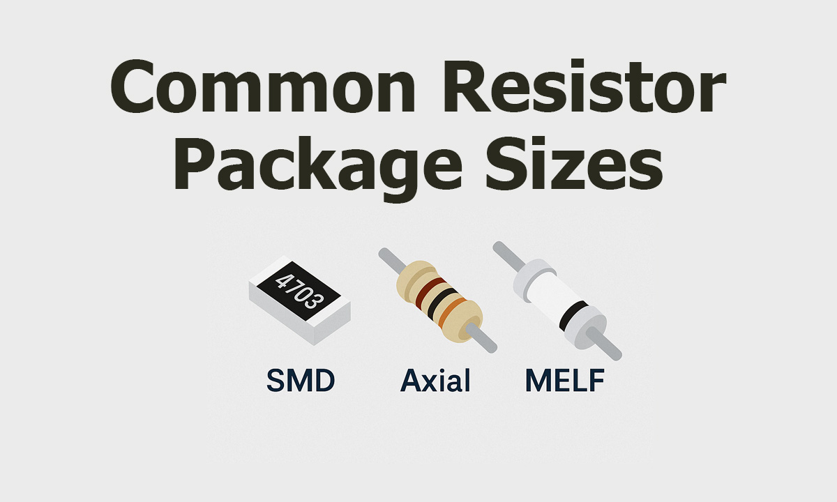
When you’re laying out a PCB or sourcing components in bulk, “what size is this resistor?” is not a trivial question. Package size affects power rating, heat dissipation, pick-and-place yields, and even whether your automatic lead forming machine can handle the part without cracking the body.
This guide walks through the most common resistor package sizes—SMD, through-hole, and MELF—with dimensions, typical power ratings, and selection tips you can actually use in design and procurement.
For both engineers and purchasing teams, package size drives several key factors:
In other words, you’re not just choosing “0603 vs 0805”; you’re choosing power margin, line capability and long-term reliability.
Modern designs mostly use rectangular SMD chip resistors standardized by JEDEC / EIA. Their size is encoded by a four-digit number like 0603, which represents length and width in mils (thousandths of an inch): 0.060″ × 0.030″. EEPower
Despite the imperial naming, PCB layout usually uses metric dimensions (mm), so you always see both units in datasheets.
Axial (THT) resistors are still widely used in power supplies, industrial boards and legacy designs. Here, the physical size is mostly tied to power rating—1/8 W, 1/4 W, 1/2 W, 1 W, etc.—and different manufacturers use very similar dimensions. EEPower+1
MELF (Metal Electrode Leadless Face) resistors are cylindrical SMT parts. They offer very good stability and low temperature coefficient but are trickier for pick-and-place because they can “roll”. Typical sizes include MicroMELF, MiniMELF and standard MELF, each with defined length, diameter and power range. EEPower
The table below summarizes the most widely used SMD packages, based on JEDEC-style dimensions and typical power ratings compiled from industry references. EEPower
| Code (Imperial) | Metric Code | Length (in) | Length (mm) | Width (in) | Width (mm) | Height (mm) | Typical Power Rating* |
|---|---|---|---|---|---|---|---|
| 0201 | 0603 | 0.024 | 0.6 | 0.012 | 0.3 | 0.25 | 1/20 W (0.05 W) |
| 0402 | 1005 | 0.040 | 1.0 | 0.020 | 0.5 | 0.35 | 1/16 W (0.062 W) |
| 0603 | 1608 | 0.060 | 1.55 | 0.030 | 0.85 | 0.45 | 1/10 W (0.10 W) |
| 0805 | 2012 | 0.080 | 2.0 | 0.050 | 1.2 | 0.45 | 1/8 W (0.125 W) |
| 1206 | 3216 | 0.120 | 3.2 | 0.060 | 1.6 | 0.55 | 1/4 W (0.25 W) |
| 1210 | 3225 | 0.120 | 3.2 | 0.100 | 2.5 | 0.55 | 1/2 W (0.50 W) |
| 1812 | 3246 | 0.120 | 3.2 | 0.180 | 4.6 | 0.55 | 1 W |
| 2010 | 5025 | 0.200 | 5.0 | 0.100 | 2.5 | 0.60 | 3/4 W (0.75 W) |
| 2512 | 6332 | 0.250 | 6.3 | 0.120 | 3.2 | 0.60 | 1 W |
*Always check the exact power rating in the manufacturer’s datasheet—values above are typical, not guaranteed.
If you’re new to SMT design, start from 0603 or 0805 unless you’re forced smaller by space or by an existing BOM.
For axial resistors, power rating is the main driver of body size. EEPower’s axial size table gives a good indication of typical dimensions for carbon or metal film resistors: EEPower
| Power Rating (W) | Body Length (mm) | Body Diameter (mm) | Lead Length (each side, mm) | Lead Diameter (mm) |
|---|---|---|---|---|
| 1/8 (0.125) | ≈ 3.0 | ≈ 1.8 | ≈ 28 | ≈ 0.45 |
| 1/4 (0.25) | ≈ 6.5 | ≈ 2.5 | ≈ 28 | ≈ 0.60 |
| 1/2 (0.5) | ≈ 8.5 | ≈ 3.2 | ≈ 28 | ≈ 0.60 |
| 1 | ≈ 11 | ≈ 5.0 | ≈ 28 | ≈ 0.80 |
A separate industry reference also links these sizes to typical lead spacing on the PCB, for example: AnyPCBA
Again, exact values vary by manufacturer and resistor type (carbon film, metal film, wire-wound), so always confirm in the datasheet.
If you’re running high-volume axial lines, it’s worth standardizing around a few power ratings and sizes that your forming and insertion equipment handle best.
MELF resistors are cylindrical SMT parts, often used where you need higher stability and better temperature coefficient than typical thick-film chip resistors. EEPower’s MELF overview summarizes three common packages: EEPower
| Package Name | Abbreviation | Code | Length (mm) | Diameter (mm) | Power Range (W) |
|---|---|---|---|---|---|
| MicroMELF | MMU | 0102 | 2.2 | 1.1 | 0.2 – 0.3 |
| MiniMELF | MMA | 0204 | 3.6 | 1.4 | 0.25 – 0.4 |
| MELF | MMB | 0207 | 5.8 | 2.2 | 0.4 – 1.0 |
MELF is less common in mainstream consumer designs because:
However, in precision, high-stability or high-temperature circuits, MELF can still be the right choice.
Physical size is only half the story. The actual resistance values available in each package follow standardized E-series value sets defined by IEC 60063 (E6, E12, E24, E48, E96, E192). 维基百科
For example, the E24 series (5% tolerance) uses values like:
1.0, 1.1, 1.2, 1.3, 1.5, 1.6, 1.8, 2.0, 2.2, 2.4, 2.7, 3.0, 3.3, 3.6, 3.9, 4.3, 4.7, 5.1, 5.6, 6.2, 6.8, 7.5, 8.2, 9.1 维基百科
Most SMD and THT resistor families offer a subset of these values, so when you pick a package (say 0603 for 1/10 W), you’ll normally have a standard E24 or E96 value set available in that package.
When you’re choosing a resistor package size for a real design, a simple, practical workflow is:
If your production line includes automatic resistor lead forming machines, package and lead geometry are not theoretical—they define whether your line runs smoothly:
Standardizing packages (for example, using mostly 1/4 W and 1/2 W axial resistors on THT lines) simplifies both tooling setup and inventory management and reduces scrap in high-volume production. AnyPCBA
To go deeper and connect package size to your broader component and process strategy, you can refer to:
You can adapt the anchor text and exact URLs to match your existing site structure, but keeping 2–3 focused, context-relevant internal links like these helps both SEO and user navigation.
If you align electrical requirements, PCB constraints and assembly capability, picking the “right” resistor package size becomes a straightforward, repeatable decision instead of a guessing game.
The most common SMD resistor package sizes are 0402, 0603, 0805 and 1206. They follow JEDEC standards for length and width and each size has a typical power rating, from around 1/16 W up to 1/4 W or more depending on the series and manufacturer.
Start from the required power dissipation and apply a comfortable derating factor. Then consider PCB space, assembly method and automation. For dense digital circuits, 0402 or 0603 usually work well. For higher current or higher temperature, larger sizes like 0805, 1206 or 2512—or axial through-hole resistors—provide more power margin.
Both are common SMD chip resistor packages, but 0805 is physically larger and can usually handle more power than 0603. 0603 saves PCB space but has smaller pads and slightly lower power rating, while 0805 offers easier assembly and more robust power handling in many power supply and industrial applications.
Yes. Axial resistor body length and diameter roughly scale with power rating, such as 1/4 W, 1/2 W and 1 W. Exact dimensions vary by manufacturer, but most follow similar size families so that automated lead forming and PCB hole spacing remain compatible.
When you’re just getting

Choosing the right capaci
A capacitor lead cutter i

Capacitor lead forming ma

Charger and power adapter

If your through-hole (rad