Incoming component
Components enter in bulk, on tape or reels, in tubes or trays, or by manual loading.

Plan the right feeding, cutting, bending, inspection and automation solution around your actual components—not a generic machine specification.
It converts an incoming electronic component into a repeatable, PCB-ready part through controlled feeding, lead cutting, forming, inspection and discharge.
A forming system may perform one operation or combine several operations in one continuous process.
Components enter in bulk, on tape or reels, in tubes or trays, or by manual loading.
Each component is fed and oriented consistently before forming.
Lead length, lead pitch and final geometry are controlled to requirements.
The formed component is inspected, discharged or transferred onward.
Improve consistency, output and process control.
Control lead length, pitch, bend angle and stand-off.
Move repetitive cutting, bending, feeding and collection away from manual work.
Stabilize cycle time and reduce rework interruptions.
Reduce lead cracks, body damage and insertion problems.
Connect forming with sleeving, welding, inspection or sorting.
Use adjustable dimensions, tooling and recipes for an agreed range.
After clarifying what the forming process must achieve, match the component structure and required operations to the correct Flourishe equipment category.
Machine families are classified by component structure and required operations—not by automation level.
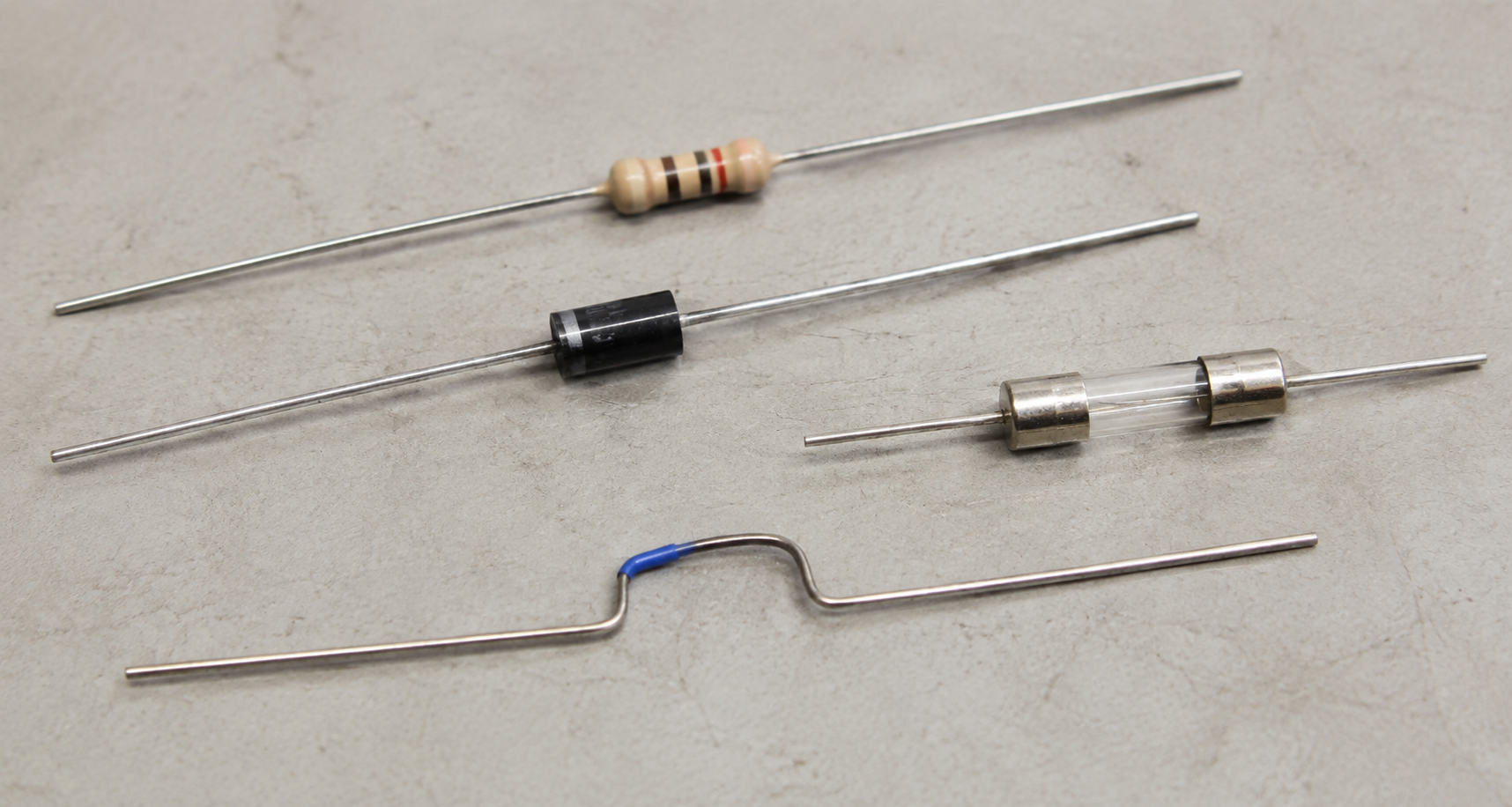
Cutting, horizontal or vertical forming, U/F/UK shapes and lead-pitch control.
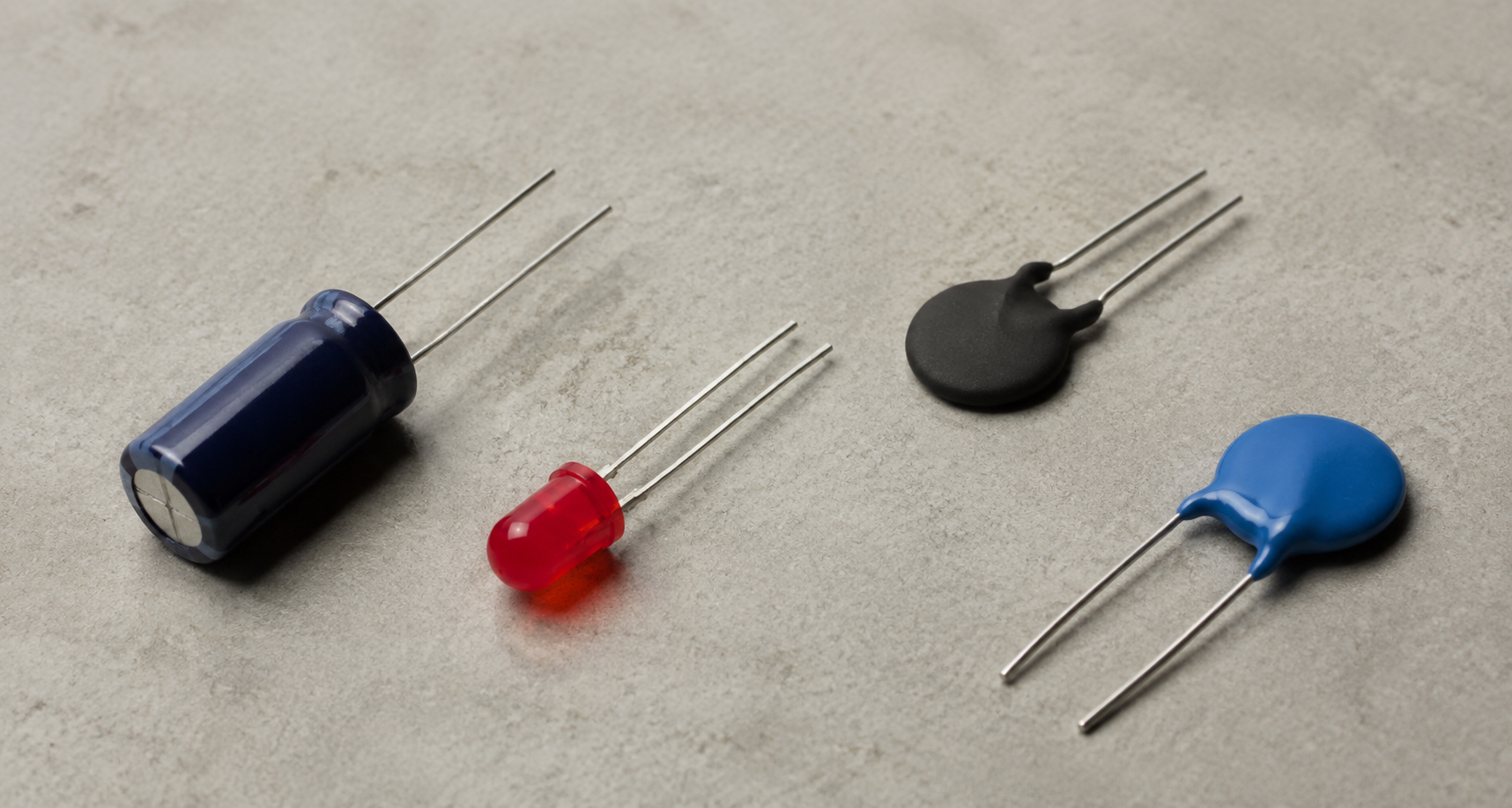
Lead cutting, pitch adjustment, kink, stand-off and radial forming.
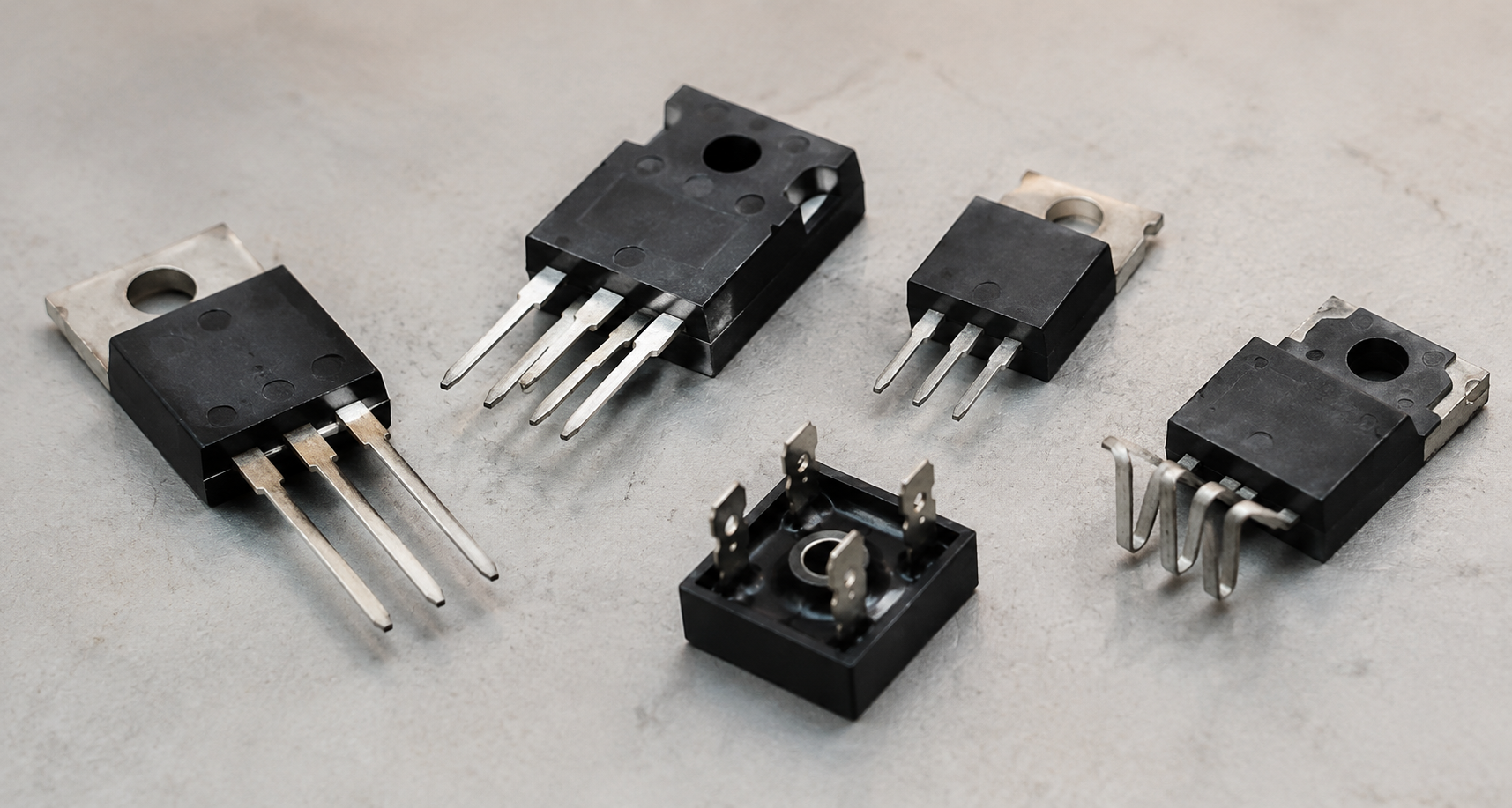
Multi-step forming, material application, positioning, inspection and fastening.
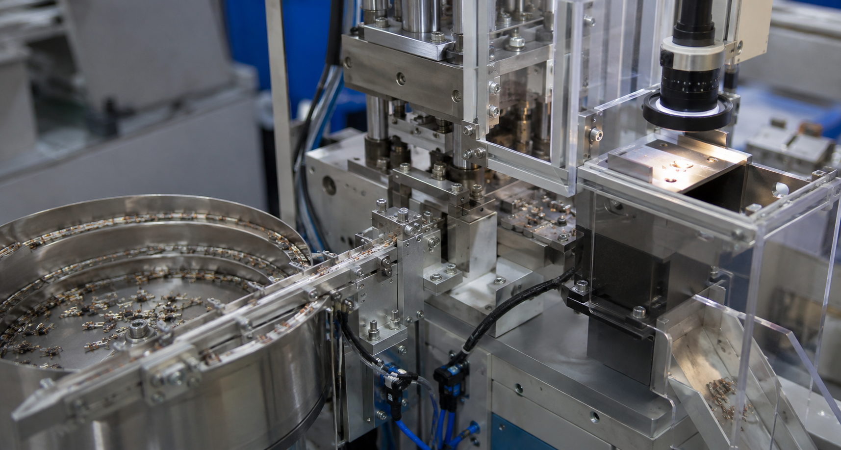
Forming combined with welding, sleeving, inspection, sorting or line transfer.
After selecting the correct component/process family, choose how much operator involvement should remain: manual, pneumatic, semi-automatic or fully automatic.
Automation level should be selected after the component family and forming process are clear.
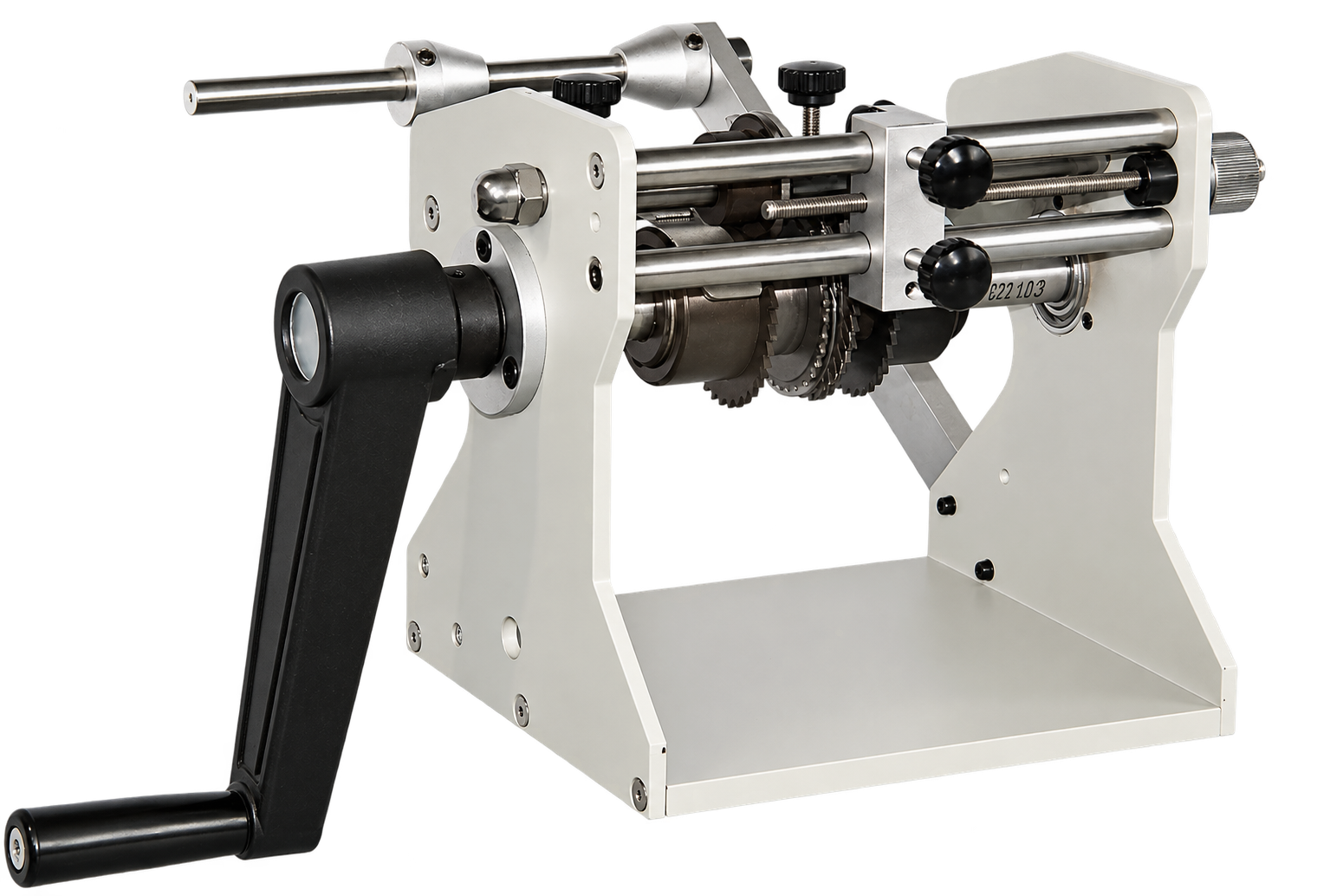
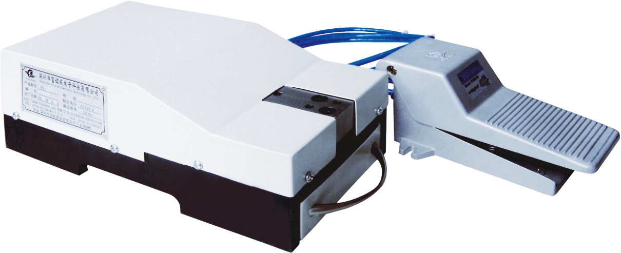
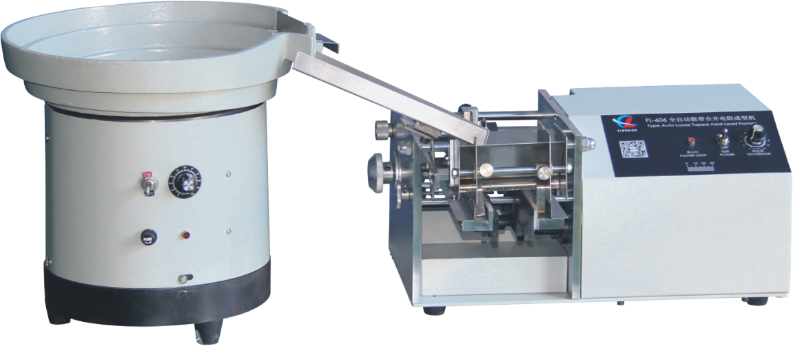
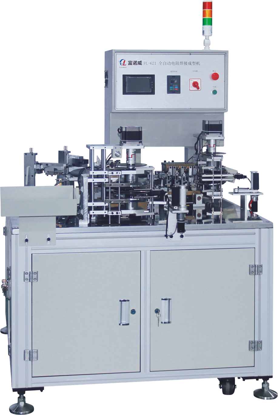
A custom machine is valuable when the component, feeding, inspection or connected process cannot be handled reliably by an existing platform.
Common component type, conventional geometry and compatible dimensions
Lower engineering risk · shorter lead time · lower investmentProven forming principle with special tooling, feeding, inspection or model-range requirements
Balances proven architecture with targeted customizationSpecial geometry, difficult feeding, strict tolerance or several integrated operations
Highest flexibility with more engineering, testing, cost and lead time| Consideration | Standard machine | Modified standard | Non-standard custom |
|---|---|---|---|
| Component & forming geometry | Common and within published range | Related part with special dimensions/tooling | Unusual structure or multi-step geometry |
| Incoming material & feeding | Compatible with existing method | Dedicated guide, fixture or feeder module | Difficult bulk separation or orientation |
| Tolerance & inspection | Within standard capability | Added gauge, sensor or vision check | Closed-loop inspection and project-specific criteria |
| Model range & changeover | Existing adjustments/tooling | Quick-change tooling and recipes | Architecture designed for the agreed component family |
| Connected operations | Usually one main operation | One or two added modules | Forming plus welding, sleeving, assembly or transfer |
| Engineering risk & lead time | Lowest / shortest | Medium | Highest / longest |
Once the required machine scope is clear, estimate annual savings, payback period and expected return before approving the investment.
Customization combines component data, feeding, tooling, automation, quality, factory integration and economic value.
Body dimensions, lead material, pitch, cutting length, bend position, radius, angle, stand-off and tolerance.
Bulk, tape, tube, tray or manual loading; tangling, polarity, orientation and incoming variation.
Straightening, cutting, U/F/UK forming, kink, 90-degree or multi-step forming and component protection.
Operator involvement, feeding logic, recipes, changeover, alarms and required production data.
Critical dimensions, cosmetic limits, inspection method, sorting logic and measurable FAT criteria.
Footprint, utilities, upstream and downstream interfaces, labor, output, investment and target payback.
A reliable proposal needs enough information to define function, measurable quality and real operating conditions.
Get the requirements checklistPart number or component type, datasheet, body dimensions, lead diameter and material, plus representative samples.
Bulk, tape, tube or tray; orientation, polarity, packaging and incoming variation.
Drawing, lead pitch, lead length, bend position, angle, bend radius, stand-off and tolerances.
Required output in parts per hour, shift pattern, number of models, changeover frequency and target yield.
Critical dimensions, cosmetic limits, crack prevention, inspection and traceability.
Power, air, footprint, safety, language, interfaces and destination country.
A staged process documents assumptions and gives both teams measurable review and approval points.
Share parts, drawings, forming dimensions, tolerances and target output.
Evaluate feeding behavior, tooling requirements, quality risks and cycle time.
Receive a defined process, machine configuration, scope, timeline and quote.
Mechanical systems, controls, tooling and software are built as one system.
Production-representative parts validate accuracy, repeatability and stability.
Verify acceptance criteria before shipment, installation, training and support.
Start with current production costs, set a target payback period and add the complete installed project cost when a quotation is available.
Annual net savings
(Labor + quality savings) × (1 − safety margin) − added operating cost
Investment ceiling
Annual net savings × target payback months ÷ 12
Payback after quotation
Total installed project cost ÷ annual net savings × 12
Three-year ROI
(Three-year net savings − project cost) ÷ project cost × 100%
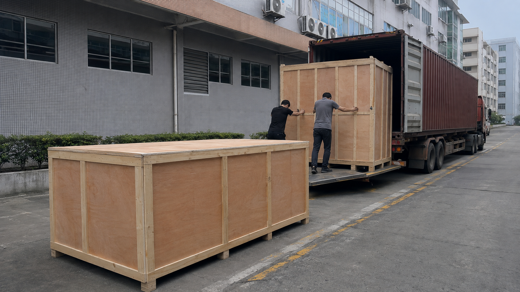
Sample trials and factory acceptance testing translate requirements into measurable acceptance criteria.
Every project begins with the customer’s components, output, available space and process requirements. These representative cases show how we select the appropriate automation level and customize only where it creates practical value.
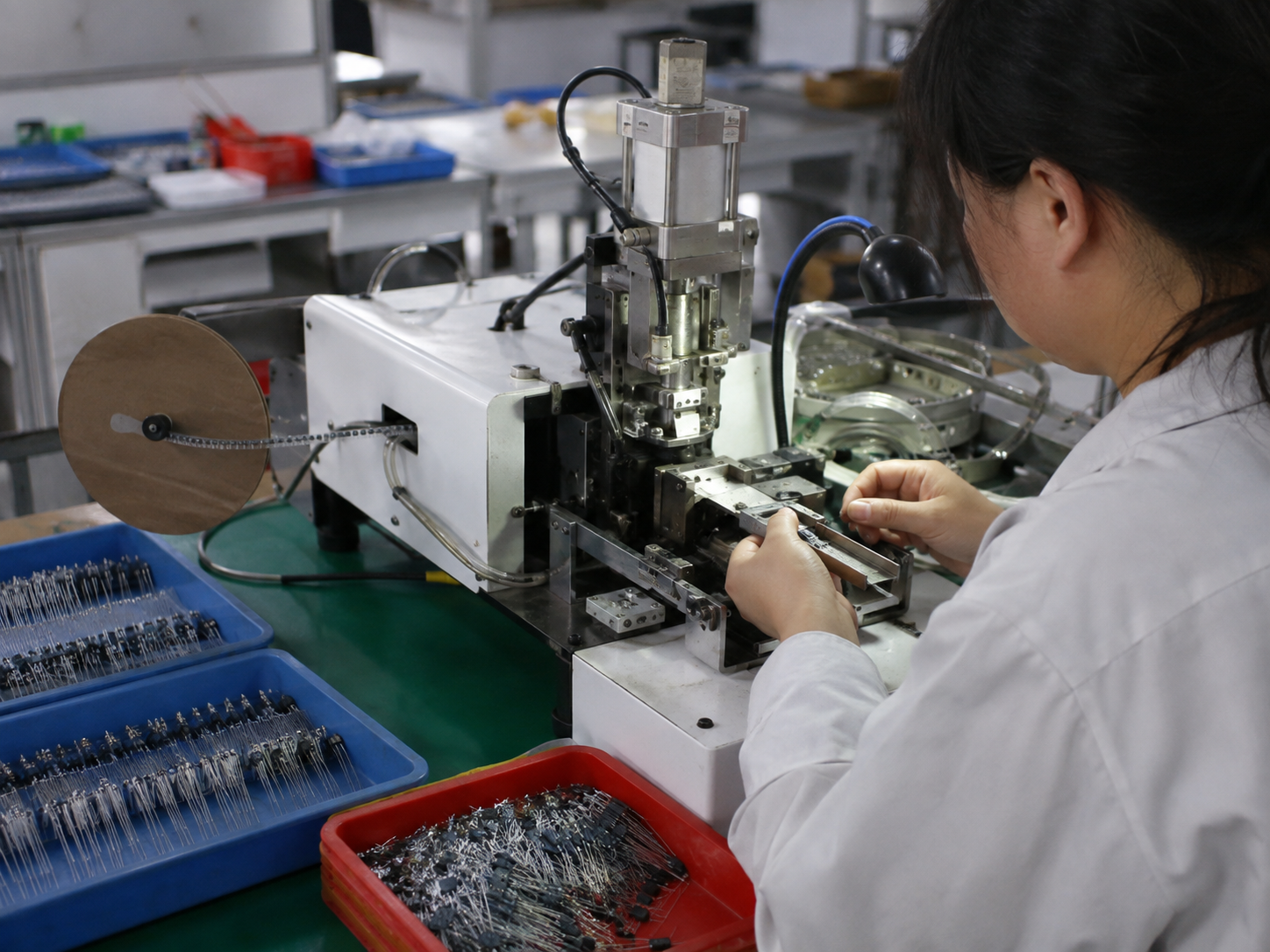
The customer wanted to replace inconsistent manual lead cutting and forming, but demand was not continuous enough to keep a fully automatic feeder utilized. Model changes were frequent and operators were still available for loading.
Batch size, daily output, changeover frequency, labor availability and the cost difference between operator loading and automatic feeding.
The feeding system would add cost, footprint and changeover work without creating enough additional productive hours to justify it.
The required consistency was addressed while avoiding unnecessary feeder and integration investment. The customer retained flexible changeovers and a clearer path to upgrade if volume grows.
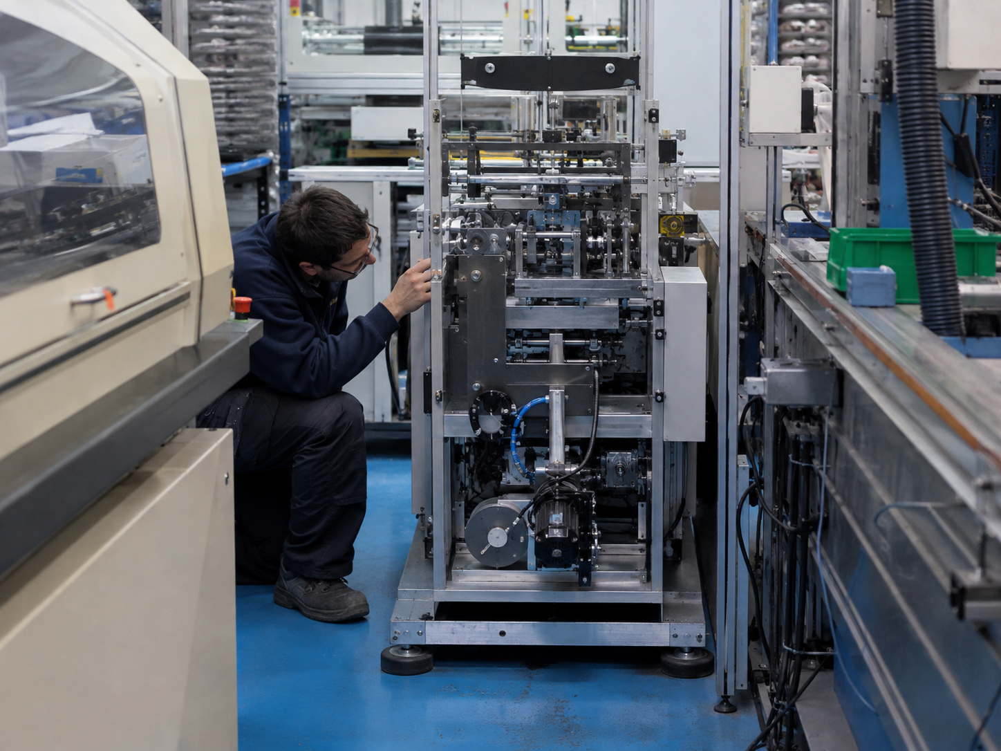
The forming process was conventional, but a standard machine layout would obstruct the aisle and require the operator to move material around the cell. The discharge height also had to match an existing downstream fixture.
Available footprint, access for maintenance, operator reach, incoming and outgoing material direction, utilities and downstream interface height.
The standard forming core was retained while the feeder position, control cabinet, discharge direction and frame layout were adapted to the site.
The solution could be introduced into the intended cell without a wider line rearrangement. Keeping the proven forming module also limited engineering risk and simplified future maintenance.
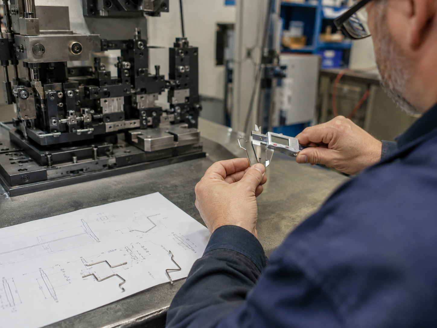
The required shape combined an offset bend, controlled stand-off and short remaining lead length. Component bodies and leads varied between models, making a catalogue machine specification insufficient.
Actual samples, 2D drawings, tolerance stack, lead material and diameter, body protection, bend sequence, springback and acceptable cosmetic condition.
Forming trials were used to confirm datum points and bend order before finalizing dedicated tooling, guides and programmable motion.
The customer gained a repeatable process defined around approved samples and acceptance criteria, rather than relying on operator adjustment or purchasing a general machine that could not guarantee the shape.
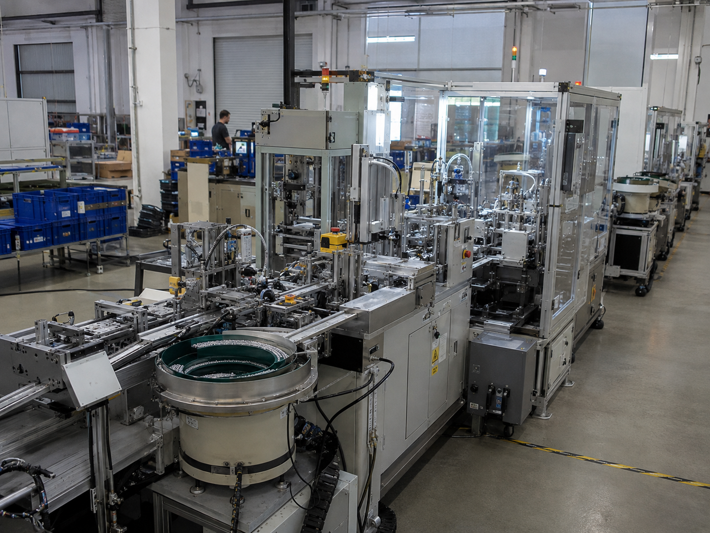
Forming, applying material, positioning, inspection and final assembly were performed at separate stations. Parts were repeatedly collected and reloaded, increasing work-in-process and making defect traceability difficult.
Cycle-time balance, process sequence, buffers, inspection points, reject handling, model change, upstream supply and downstream acceptance requirements.
Unlike the moderate-volume case, stable demand and repeated transfers meant that combining operations addressed both labor and process-control problems.
The proposed process reduced separate handling points, established clear inspection and reject logic, and created a scalable production flow. Integration scope remained tied to validated requirements rather than adding automation for its own sake.
About these examples: They are representative decision scenarios, not claims of identical results for every project. Final configuration, output and commercial value must be confirmed from actual samples, drawings, incoming format, site conditions and agreed acceptance criteria.
Discuss your applicationNot always. We first check whether a standard platform or a modified standard machine can meet the component, feeding and acceptance requirements.
Provide representative samples, drawings, incoming packaging, target formed dimensions, tolerances, output requirements and any required downstream operations.
Often yes, when the agreed component family can be covered by adjustable dimensions, replaceable tooling, guides and saved recipes.
Acceptance should be based on agreed dimensions, quality risks, output rate, continuous-run stability, sorting logic and safety functions.
Each supporting article can expand a comparison, checklist or cost question without interrupting the main buying logic.
Compare throughput, labor requirements, repeatability, rework cost and the production conditions that justify automation.
Read guide →Understand the differences in component type, forming function, applications and equipment selection.
Read guide →Prepare component samples, drawings, incoming format, output targets and acceptance requirements for an accurate quotation.
Read guide →Send your component specifications, final formed-part drawing, target output and sample availability. Our engineering team will identify the most suitable standard, modified-standard or fully custom solution.