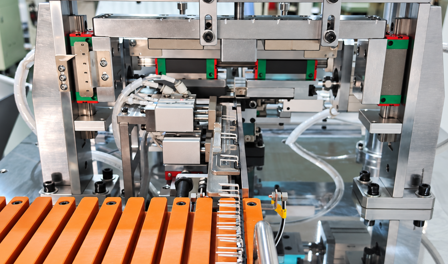
A reliable transistor lead forming machine should produce leads within the specified drawing tolerances without cracking the component body, damaging the lead plating, or causing unstable PCB insertion. The correct machine is determined by the transistor package, incoming packaging, required forming shape, dimensional tolerance, production volume, and changeover frequency—not simply by the machine’s advertised speed or purchase price.
Before placing an order, provide the supplier with actual component samples and a finished-part drawing. The drawing should specify the lead length, pitch, bend position, forming height, bend angle, and allowable tolerances. The supplier should then demonstrate continuous sample production using the proposed feeding system and tooling.
For purchasing evaluation, compare machines using the following five points:
- Whether the feeding system matches bulk, tube-packed, taped, or loose components
- Whether one cycle can complete cutting, bending, spreading, offset forming, or other required operations
- Whether the machine maintains dimensional consistency during continuous production
- How much time and operator adjustment are required for product changeover
- Whether tooling, wear parts, technical support, and replacement components will remain available after delivery
A machine should be approved based on qualified output rather than no-load speed. During the acceptance test, record the number of conforming parts produced over a defined period, along with dimensional variation, feeding interruptions, package damage, and lead-surface defects. These results provide a more reliable basis for comparing equipment than rated speed alone.
1. Start With the Actual Transistor, Not Just the Package Name
“TO-220 forming machine” or “TO-92 cutting machine” is not enough information for machine selection.
Components using the same nominal package may differ in:
- Body width and thickness
- Lead width and thickness
- Lead pitch
- Lead material and plating
- Metal-tab dimensions
- Position of the mounting hole
- Pin arrangement
- Incoming lead condition
- Packaging method
The supplier should receive the complete manufacturer and part number, component datasheet, package drawing, and physical samples.
For example, the official onsemi TO-220 mechanical outline shows that package selection must be based on defined dimensional ranges rather than one nominal value.
If the factory uses the same transistor package from several suppliers, samples and drawings from each supplier should be evaluated. A feeding track or locating fixture designed around one brand may not reliably process another brand.
Information to Confirm
| Item | Required information |
|---|---|
| Component | Manufacturer and complete part number |
| Package | TO-92, TO-220, TO-247, TO-3P, or another type |
| Incoming dimensions | Minimum, nominal, and maximum values |
| Pin definition | Gate, drain, source or base, collector, emitter |
| Lead condition | Straight, preformed, plated, or partially cut |
| Packaging | Bulk, tube, tray, or customer-specific packaging |
| Suppliers | Single source or multiple approved sources |
2. Define the Finished Component Before Selecting the Machine
A supplier cannot design reliable tooling from a description such as “bend the leads 90 degrees” or “cut the pins shorter.”
The finished drawing should identify:
- Forming direction
- Finished lead length
- Finished lead pitch
- Body-to-bend distance
- Bend angle
- Bend radius
- Offset distance
- Standoff height
- Lead coplanarity
- Dimensional tolerances
- Permitted tool marks
- Inspection datum
If a finished drawing is unavailable, provide:
- Original transistor
- PCB
- Heatsink, if applicable
- Correctly assembled product
- Approved formed sample
The supplier can then prepare a proposed finished-component drawing for customer approval.
Why the Datum Matters
A dimension such as “10 mm lead length” is incomplete unless the starting point is defined.
The dimension may be measured from:
- The package body
- The lead exit
- The first bend
- The second bend
- The lead tip
- A PCB or heatsink reference surface
Both sides must use the same datum during tooling design, sample approval, and final inspection.
3. Evaluate the Feeding System Separately
In many automatic forming projects, the forming action is not the main source of downtime. Feeding is.
A machine may complete the forming cycle correctly but still fail to maintain production if components overlap, rotate, jam, or arrive at the forming station in the wrong orientation.
Bulk Feeding
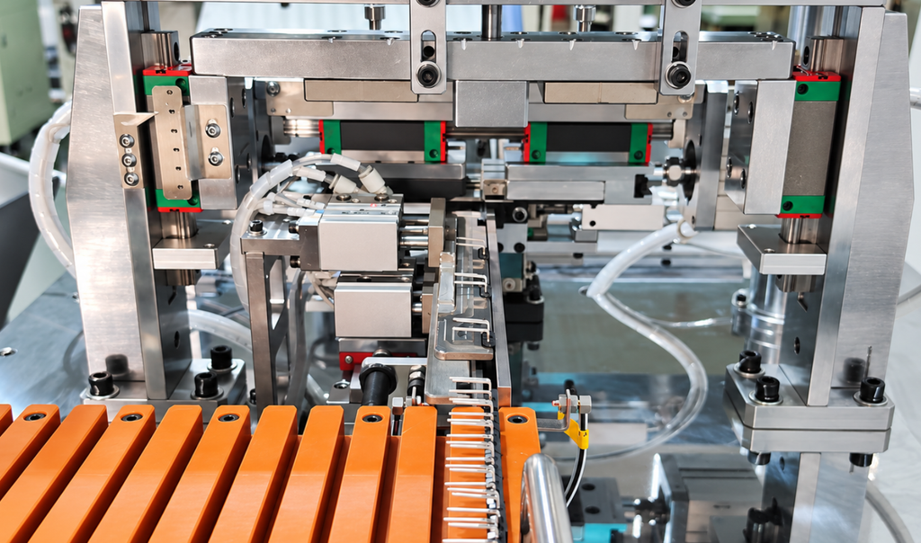
Bulk transistors normally require a vibratory bowl and linear feeding track.
The supplier should evaluate:
- Whether the leads become entangled
- Whether the components overlap
- Whether reversed parts can enter the track
- Whether bent incoming leads create jams
- Whether package variation affects track clearance
- Whether bowl speed matches machine cycle speed
- Whether refilling interrupts production
Bulk feeding should be tested with enough components to reproduce actual production conditions.
A short test with a small, carefully selected sample does not prove feeding stability.
Tube Feeding
Tube-packed power transistors are already arranged in one direction, but the tube feeder must still match the actual packaging.
Confirm:
- Tube cross-section
- Tube length
- Components per tube
- Stopper design
- Component orientation
- Clearance inside the tube
- Tube material and rigidity
- Variation between packaging suppliers
- Number of tubes loaded at one time
- Method used to detect an empty tube
Actual production tubes should be sent to the machine supplier. Photographs alone are not enough for final feeder design.
Questions to Ask About Feeding
- Has the feeder been tested with our exact components?
- How many components were used during the test?
- Can reversed components be detected?
- How does the machine handle bent incoming leads?
- What happens when the track is empty?
- Can the feeder accommodate components from another approved supplier?
- Which feeding parts must be changed when the package changes?
- How long can the machine run without operator intervention?
4. Check Repeatability, Not Just One Finished Sample
One correctly formed transistor only proves that the machine can perform the process once.
Production reliability means the machine can repeatedly maintain:
- Finished lead length
- Lead pitch
- Bend position
- Bend angle
- Offset height
- Standoff height
- Lead coplanarity
- Package orientation
Samples should be measured at different times during a continuous test.
| Sampling point | Purpose |
|---|---|
| Beginning of production | Confirms the initial setup |
| Middle of production | Detects gradual dimensional drift |
| End of production | Checks stability after extended operation |
| After material refill | Checks feeding and positioning recovery |
| After alarm recovery | Checks whether the process returns correctly |
| After changeover | Confirms setup repeatability |
The supplier and customer should agree on the measuring method, inspection tools, datums, and permitted tolerances before the acceptance test.
5. Make Sure the Tooling Protects the Component
A finished component may meet the target dimensions and still be unacceptable if the forming process damages the leads or package.
Inspect for:
- Cracked plating
- Exposed base metal
- Deep tool marks
- Burrs
- Twisted leads
- Deformed lead edges
- Package scratches
- Package cracks
- Stress near the lead-to-body interface
The tooling should support the leads during cutting and bending without transferring excessive force into the package.
NASA-STD-8739.3 provides useful general guidance on supporting component leads during forming and controlling the distance between the package and the bend. The customer’s product drawing and applicable assembly standard should remain the final requirements.
Tooling Questions
Ask the supplier:
- What material is used for the cutting and forming tools?
- Which parts are hardened?
- Can the cutting blade be sharpened?
- Which tooling parts are expected to wear first?
- How are replacement tools located and aligned?
- Can the operator replace the tool without repeating a complete setup?
- Are spare cutting and forming parts included?
- What maintenance interval is recommended?
- Is lubrication required?
Tool life should not be presented as a fixed number without considering lead material, thickness, plating, forming shape, and production conditions.
6. Compare Sustainable Output, Not Maximum Cycle Speed
Published machine speed usually represents output under specified conditions. It may not include every production interruption.
Actual accepted output can be reduced by:
- Material loading
- Tube replacement
- Feeding jams
- Alarm resets
- Component rejection
- Dimensional inspection
- Finished-part collection
- Tool adjustment
- Product changeover
- Preventive maintenance
The useful production measurement is:
Accepted output = Total processed quantity − Rejected quantity − Downtime losses
During testing, record the following data.
| Test item | Required record |
|---|---|
| Continuous running time | Actual machine operating period |
| Input quantity | Total components loaded |
| Cycle count | Machine processing count |
| Accepted quantity | Components passing inspection |
| Rejected quantity | Components outside requirements |
| Number of stops | Feeding, tooling, sensor, or operator stops |
| Total downtime | Time lost during the test |
| Stop reasons | Cause of each interruption |
| Operator intervention | Actions required to continue production |
A supplier should clearly state whether the published figure is mechanical cycle speed or verified accepted output.
7. Consider Product Changeover Before Choosing Automation
A machine optimized for one product can become inefficient in a factory with frequent product changes.
Before selecting a machine, confirm:
- Number of transistor packages
- Number of part numbers
- Number of forming profiles
- Batch size for each product
- Daily or weekly changeover frequency
- Required adjustment points
- Number of tools to be replaced
- Need for recipe storage
- Need for first-piece inspection
- Skill level required from the operator
Fixed Tooling
Fixed tooling is generally suitable when:
- The same component runs for long periods
- The forming dimensions rarely change
- Production volume is stable
- Fast cycle time is more important than flexibility
Replaceable Tooling
Replaceable tooling is more suitable when:
- Several components use the same machine platform
- Production changes between batches
- Each product requires a different forming shape
- Tool replacement can be completed using repeatable locating features
Multiple Preset Tool Positions
A machine with several installed tool sets can reduce the time required to switch among established forming profiles.
For example, the FL-955 can be configured with multiple forming-tool positions. This is useful when the factory repeatedly produces a limited number of confirmed products.
It does not mean that one tool can process every package or lead shape. Each forming profile still requires engineering confirmation.
8. Select the Appropriate Automation Level
The most automated machine is not automatically the most reliable or economical choice.
Pneumatic Forming Machine
A pneumatic machine is generally suitable when:
- Production volume is low or moderate
- Products change frequently
- Components are difficult to feed automatically
- Manual loading is acceptable
- Initial investment must remain controlled
- One-cycle cutting and forming are required
Advantages:
- Compact structure
- Lower initial cost
- Simple maintenance
- Flexible custom tooling
- Faster project development
Limitations:
- Operator-dependent loading
- Lower output
- Greater variation between operators
- Limited automatic counting and inspection
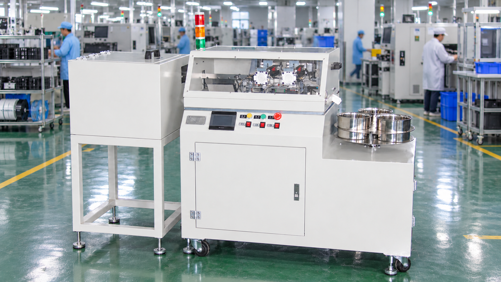
The FL-900 is an example of a compact pneumatic platform for custom component cutting and forming.
Fully Automatic Forming Machine
A fully automatic machine is more suitable when:
- Production quantities are stable
- The same components run for long periods
- Labor reduction is important
- Automatic counting is required
- Continuous feeding can be achieved
- Dimensional consistency must be maintained across shifts
Advantages:
- Reduced manual handling
- More consistent operating cycle
- Automatic feeding and counting
- Higher production capacity
- Easier integration with downstream equipment
Limitations:
- Higher initial cost
- Product-specific feeding system
- More complex changeover
- Greater need for stable incoming materials
The FL-950 is designed primarily for automatically feeding and forming TO-92 components. The FL-955 is intended for larger power-transistor applications using bulk feeding, with tube-feeding customization available.
Integrated Forming and Assembly Machine
An integrated system may be justified when the formed transistor immediately proceeds to:
- Thermal grease application
- Insulating-pad placement
- Heatsink positioning
- Screw fastening
- Electrical or visual inspection
Integration reduces intermediate handling but requires stable component and assembly designs.
If transistor models, heatsinks, or screw positions change frequently, a highly integrated machine may require more complex fixtures and longer changeovers.
9. Check the Control and Alarm System
A stable mechanical structure is not enough. The control system must detect abnormal conditions before defective components continue through production.
Useful detection functions include:
- Component presence
- Component orientation
- Feeding-track shortage
- Empty tube
- Separator position
- Tool position
- Air-pressure status
- Collection-box status
- Safety-door status
- Motor or cylinder faults
The machine should clearly show:
- Alarm location
- Alarm cause
- Recovery procedure
- Affected component
- Whether the cycle can restart safely
An unclear alarm system increases downtime because operators must search for the fault manually.
Recipe Storage
Recipe storage is useful when the same products return regularly.
A recipe may store:
- Tool position
- Feeding speed
- Timing
- Sensor settings
- Counting quantity
- Discharge method
Mechanical tooling must still be confirmed after a recipe change. Stored parameters cannot correct an incorrectly installed mold or fixture.
10. Evaluate Maintenance Access and Spare Parts
A reliable machine must be maintainable by the customer’s production team.
Check whether operators can easily access:
- Feeding tracks
- Separators
- Cutting tools
- Forming tools
- Sensors
- Pneumatic components
- Finished-part collection areas
- Lubrication points
The supplier should provide:
- Operation manual
- Maintenance manual
- Electrical drawing
- Pneumatic diagram
- Tooling drawing
- Recommended spare-parts list
- Consumable-parts list
- Alarm guide
- Training materials
Recommended Spare Parts
Depending on the machine structure, the initial spare-parts package may include:
- Cutting blades
- Forming inserts
- Springs
- Sensors
- Pneumatic seals
- Belts
- Track wear parts
- Positioning blocks
- Component-specific locating parts
Spare parts should be discussed before shipment, especially when the machine will be installed overseas.
11. Understand What Determines the Machine Price
The price of a transistor lead forming machine depends on more than the forming shape.
| Price factor | Basic configuration | Higher-cost configuration |
|---|---|---|
| Loading | Manual loading | Automatic bowl, tube, tray, or robotic feeding |
| Forming profiles | One fixed profile | Several independent forming tools |
| Product range | One package | Multiple packages or suppliers |
| Inspection | Manual sampling | Sensors or vision inspection |
| Changeover | Manual tool replacement | Quick-change or preset tooling |
| Controls | Basic pneumatic control | PLC, HMI, recipes, and data recording |
| Discharge | Simple collection box | Sorting or downstream conveyor |
| Traceability | Production count only | Batch records and factory-system connection |
| Downstream process | Forming only | Grease application, assembly, and screw fastening |
| Safety | Basic protection | Full enclosure and interlocks |
12. Calculate Total Production Cost
The lowest purchase price does not always provide the lowest long-term cost.
Total cost includes:
- Machine purchase
- Forming tools
- Feeding-system modifications
- Spare cutting tools
- Operators
- Rejected components
- Changeover downtime
- Maintenance
- Replacement parts
- Technical support
- Production losses caused by stoppages
A practical calculation is:
Annual production cost = Labor + Rejects + Downtime + Maintenance + Tooling
Cost Comparison Table
| Cost item | Existing process | Proposed machine |
|---|---|---|
| Operators per shift | ______ | ______ |
| Monthly labor cost | ______ | ______ |
| Monthly accepted output | ______ | ______ |
| Rejection rate | ______ | ______ |
| Monthly rejected-part cost | ______ | ______ |
| Monthly downtime cost | ______ | ______ |
| Annual tooling cost | ______ | ______ |
| Annual maintenance cost | ______ | ______ |
| Estimated annual total | ______ | ______ |
Return on investment should not be calculated from labor savings alone. Reduced rejects, stable output, shorter changeovers, and lower work-in-process inventory can also create value.
13. Define the Factory Acceptance Test Before Ordering
The acceptance requirements should be agreed upon before the machine is manufactured.
Use Actual Production Materials
The test should use:
- Actual transistor part numbers
- Actual production tubes or bulk components
- Components from more than one batch when possible
- Actual PCB or heatsink samples
- Approved finished-component drawings
- Agreed inspection equipment
Define the Test Conditions
| Acceptance item | Requirement to define |
|---|---|
| Continuous running time | Agreed test duration |
| Test quantity | Total components to be processed |
| Permitted stops | Maximum feeding or machine interruptions |
| Accepted output | Minimum qualified quantity per hour |
| Rejection rate | Maximum permitted percentage |
| Dimensional inspection | Dimensions, tolerances, and sampling frequency |
| Changeover | Maximum setup time and verification method |
| Alarm testing | Faults that must be simulated |
| Documentation | Manuals, drawings, and spare-parts records |
Test Abnormal Conditions
The test should also include:
- Missing components
- Reversed components
- Bent incoming leads
- Empty tubes
- Feeding jams
- Low air pressure
- Sensor faults
- Full collection box
- Emergency stop
- Restart after an alarm
A reliable machine should stop safely, identify the fault clearly, and return to production without losing the approved setup.
14. Questions to Ask the Supplier
Before placing an order, ask:
- Has the machine processed this exact part number?
- Which samples are required for evaluation?
- Can the feeder handle components from different approved suppliers?
- Is the quoted output cycle speed or accepted output?
- How long was the machine tested continuously?
- Which dimensions can be adjusted?
- Which product changes require a new tool?
- How long does a normal changeover take?
- Which parts wear most frequently?
- Can the cutting tools be sharpened?
- Which spare parts are included?
- How are reversed or missing components detected?
- Can production settings be stored as recipes?
- What happens when the feeder jams?
- Is remote troubleshooting available?
- Is on-site commissioning available?
- Which items are excluded from the quotation?
- Will actual customer materials be used for the factory acceptance test?
The supplier’s answers should be included in the technical proposal or acceptance agreement when they affect machine performance.
Transistor Lead Forming Machine Selection Checklist
| Evaluation area | Confirmed |
|---|---|
| Exact component manufacturer and part number provided | ☐ |
| Package drawing reviewed | ☐ |
| Actual samples supplied | ☐ |
| Actual tubes, trays, or bulk packaging supplied | ☐ |
| Finished-component drawing approved | ☐ |
| PCB or heatsink sample supplied | ☐ |
| Feeding method confirmed | ☐ |
| Sustainable accepted output defined | ☐ |
| Finished tolerances defined | ☐ |
| Tool material and maintenance method confirmed | ☐ |
| Changeover time confirmed | ☐ |
| Alarm and error-handling method confirmed | ☐ |
| Spare-parts list confirmed | ☐ |
| Factory acceptance conditions approved | ☐ |
| Installation and training scope confirmed | ☐ |
| Warranty and technical support confirmed | ☐ |
Frequently Asked Questions
The most important factor is whether the complete system can repeatedly process the actual component within the required tolerance.
This includes feeding, positioning, cutting, forming, inspection, and discharge.
No. A fully automatic machine provides advantages when products and production volumes are stable.
For small batches or frequent product changes, a pneumatic or semi-automatic machine may be simpler and more economical.
Differences may include the feeding system, tooling quantity, control system, inspection functions, safety configuration, spare parts, and technical support.
Compare the complete scope rather than only the machine name.
A preliminary quotation may be possible, but final feeding and tooling design normally requires physical components and actual packaging.
Automatic feeding projects require more sample verification than manually loaded machines.
No. High mechanical speed has limited value if the feeder jams frequently, changeovers are slow, or the rejection rate is high.
Sustainable accepted output is more important than peak speed.
Sometimes, but different packages may require different tracks, separators, positioning fixtures, and forming tools.
The supplier should list the exact part numbers covered by the quotation.
Run the machine continuously using actual production materials. Measure finished components at the beginning, middle, and end of the test and record feeding stops, rejects, alarms, and operator interventions.
The required quantity depends on the feeding system and test plan.
A manually loaded pneumatic machine may require fewer samples. A fully automatic machine requires enough components for feeding adjustment and continuous testing.
Conclusion
A reliable transistor lead forming machine should be selected according to the complete production process, not only by price, speed, or package name.
The final decision should consider:
- Component variation
- Feeding stability
- Finished dimensional repeatability
- Lead and package protection
- Sustainable accepted output
- Product changeover
- Tooling life
- Maintenance access
- Spare parts
- Technical support
- Total production cost
Before requesting a final proposal, provide the actual transistor, incoming packaging, finished-component drawing, PCB or heatsink sample, production target, and acceptance criteria.
A machine tested with real customer materials and a clearly defined acceptance standard is more reliable than one selected only from a catalog specification.