When requesting a quotation for a component forming machine, it may be tempting to send only a component name, a photo, and a target price. That may be enough for a rough estimate, but it is rarely enough for a reliable technical and commercial proposal.
The same resistor, capacitor, transistor, diode, or other leaded component can require very different feeding, cutting, bending, inspection, and collection methods. Small differences in lead diameter, body dimensions, incoming packaging, forming geometry, output requirements, or inspection standards can change the entire machine configuration.
A reliable quotation should therefore answer more than one question: How much will the machine cost? It should also clarify what the machine will process, what it will produce, how fast it must run, how quality will be verified, and what conditions it must work under.
This guide explains the information a machine supplier needs to develop an accurate quotation and reduce avoidable changes later in the project.
Why a Component Name Alone Is Not Enough
Terms such as “resistor forming machine” or “capacitor lead cutting machine” describe only a broad equipment category. They do not define the actual application.
For example, two customers may both need axial resistor forming, but one receives components in taped reels and requires simple 90-degree bending, while the other uses loose components, needs vertical forming, and requires automatic counting and tray collection. These are not minor options added to the same machine. They may require different feeders, mechanisms, controls, tooling, and layouts.
The more accurately the application is defined before quotation, the more dependable the proposed price, cycle time, delivery schedule, and acceptance plan will be.
1. Physical Component Samples
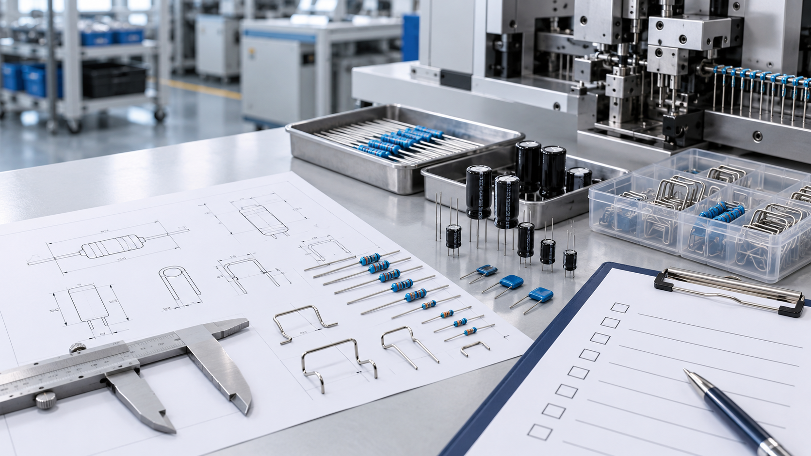
Actual samples are one of the most valuable inputs for machine evaluation. Drawings describe nominal dimensions, but samples reveal real production conditions that may not appear on paper.
Whenever possible, provide enough samples to represent normal batch variation, not only a few ideal components. The supplier may need samples for measurement, feeding tests, tooling trials, and final machine validation.
Samples help evaluate:
- Body shape, dimensions, and surface condition
- Lead material, diameter, hardness, and straightness
- Pitch and dimensional variation between batches
- Center-of-gravity and orientation behavior during feeding
- Whether leads are oxidized, coated, fragile, or easily scratched
- Deformation caused by tape, reel, bag, box, or bulk packaging
- Differences between components that appear similar in a drawing
If you process several component models, label each sample clearly and indicate the expected production share of each model. This helps the supplier distinguish the main product from occasional variants and decide whether changeover tooling is practical.
If samples cannot be shipped at the initial stage, provide clear photos and videos with a ruler or other dimensional reference. However, physical samples should normally be supplied before final design approval.
2. Component and Forming Drawings
A complete quotation requires both the incoming-component drawing and the required formed-part drawing. The supplier needs to understand the difference between the component before and after processing.
The incoming-component drawing should include, where applicable:
- Body length, width, height, or diameter
- Lead diameter and material
- Original lead length
- Lead pitch
- Dimensional tolerances
- Component polarity or directional features
- Sensitive surfaces or areas that cannot be clamped
- Approved component manufacturers and model numbers
The finished-part drawing should define:
- Final lead length
- Formed pitch or span
- Bend angle
- Bend radius
- Distance from the component body to the first bend
- Horizontal, vertical, or offset forming geometry
- Cutting position
- Coplanarity, symmetry, and straightness requirements
- Critical dimensions and their tolerances
A marked photograph can support the drawing, but it should not replace dimensioned technical documentation. If the required geometry is based on a printed circuit board, a PCB drawing or hole-location diagram can also help verify whether the formed component will fit the actual assembly.
3. Incoming Packaging and Feeding Method
How components arrive at the machine directly affects the feeding system and overall machine cost. Clearly identify whether the components are supplied as:
- Loose or bulk parts
- Taped axial components
- Radial tape-and-reel components
- Tubes, trays, sticks, or magazines
- Pre-arranged parts from an upstream machine
- Multiple packaging formats from different suppliers
For taped components, provide tape pitch, reel size, tape width, lead spacing, and winding direction. For bulk components, provide photos or videos showing how parts are packed and whether leads become tangled or bent during transportation.
Also explain how the finished components should leave the machine. Common options include bulk collection, counted batches, trays, magazines, conveyor transfer, or direct connection to the next process.
4. Product Range and Changeover Requirements
One machine may need to process a single stable component or a family of components with different body sizes and forming dimensions. These two cases lead to very different design decisions and may determine when a custom component forming machine is needed.
Prepare a product list showing:
| Item | Information to Provide |
|---|---|
| Component model | Manufacturer and part number |
| Body dimensions | Minimum, nominal, and maximum values |
| Lead dimensions | Diameter, length, pitch, and material |
| Required forming | Final dimensions and tolerances |
| Packaging | Bulk, tape, reel, tube, tray, or other |
| Production share | Approximate percentage of total volume |
| Changeover frequency | Per shift, daily, weekly, or occasional |
Ask whether changeover must be tool-free, recipe-controlled, or completed within a specific time. If operators will change tooling, define whether mistake-proofing, barcode identification, or stored parameter recipes are required.
A realistic product range is important. Designing for every possible future component can make a machine unnecessarily complex and expensive. It is often better to define the current range, likely future models, and optional expansion separately.
5. Output and Production Targets
“High speed” is not a measurable requirement. A useful output target should be based on actual production demand and operating time.
Provide the following information:
- Required good parts per hour or per minute
- Daily or monthly production volume
- Number and length of shifts
- Expected product mix
- Available operators
- Planned utilization rate
- Maximum acceptable changeover time
- Whether the target refers to theoretical speed or sustained qualified output
The required cycle rate can be estimated as:
Required output per hour = daily demand ÷ effective production hours
Effective production hours should exclude planned breaks, changeovers, maintenance, material replenishment, and other known downtime. A machine quoted only on maximum mechanical speed may fail to meet real output once these losses are considered.
It is also important to identify the current bottleneck. In some projects, the main goal is not maximum speed but reduced labor, more consistent dimensions, less material damage, faster changeover, or reliable connection to an upstream or downstream process. These factors should also be included when you calculate the ROI of a component forming machine.
6. Quality and Acceptance Criteria
A supplier cannot select suitable tooling, sensors, inspection methods, or reject mechanisms without knowing how a good part will be judged.
Define the critical-to-quality requirements before the machine is built. These may include:
- Dimensional tolerances after cutting and forming
- Maximum allowable lead or body damage
- Bend appearance and minimum bend radius
- Coplanarity and orientation
- Polarity accuracy
- Missing-part, mixed-part, or double-feed prevention
- Counting accuracy
- Acceptable defect rate
- Traceability and production-data requirements
The acceptance plan should also state how performance will be tested. Useful details include the sample quantity, run duration, component models, speed, measurement method, gauge or inspection equipment, acceptable yield, and responsibility for providing test materials.
If machine acceptance will use customer-specified capability indices, gauge repeatability studies, or internal quality standards, share those requirements during the quotation stage. Adding them after design completion may require changes to controls, tooling, and inspection systems.
7. Factory Conditions and Available Space
A machine must fit the production environment as well as the component.
Provide a layout or available-space drawing that shows:
- Maximum machine length, width, and height
- Operator position and material-loading side
- Maintenance and door-opening clearance
- Relationship to nearby machines or conveyors
- Material flow direction
- Finished-part collection area
- Floor-loading or mobility requirements
The supplier also needs to know the available power supply, voltage, frequency, compressed-air pressure, exhaust or vacuum connections, network interface, and any plant-specific connector standards.
Environmental conditions may also affect the design. Report unusual temperature, humidity, dust, vibration, cleanroom, static-control, noise, lighting, or safety requirements. Identify the destination country so the supplier can discuss applicable electrical components, labels, documentation, and compliance expectations.
8. Automation, Inspection, and Data Requirements
Not every project requires full automation. Choosing between manual, pneumatic, semi-automatic, and fully automatic forming equipment depends on volume, labor conditions, quality risk, product stability, and the surrounding production process.
Clarify which operations are included in the required scope:
- Loading and orientation
- Lead cutting and forming
- Polarity or model verification
- Dimensional or visual inspection
- Automatic reject separation
- Counting and packaging
- Marking or labeling
- Connection to a conveyor, robot, or downstream assembly machine
- Production-data collection
If the machine must communicate with a manufacturing execution system, PLC network, printer, vision system, or upstream equipment, provide the preferred protocol and interface responsibility. Also state whether you need user accounts, recipe control, alarm history, output reports, remote support, or data export.
Separating essential functions from optional functions allows the supplier to prepare a clear base quotation and properly priced alternatives.
9. Safety, Documentation, and Commercial Requirements
Technical scope is only part of a reliable quotation. State any required safety standards, guarding preferences, electrical specifications, approved component brands, and documentation language.
Typical deliverables may include:
- Operation and maintenance manuals
- Electrical and pneumatic drawings
- Spare-parts list
- Preventive-maintenance schedule
- Tooling list
- Training
- Installation and commissioning support
- Factory acceptance testing
- Site acceptance testing
- Warranty and after-sales support
Commercial requirements should cover the delivery destination, preferred trade terms, required delivery date, packaging requirements, and any site-service expectations. This information allows freight, export packaging, installation, and travel costs to be separated from the machine price instead of appearing later as unexpected additions.
A Practical RFQ Checklist
Before sending your request for quotation, check that the RFQ package includes:
- Actual samples for every main component model
- Incoming-component drawings and specifications
- Finished-part drawings with critical tolerances
- Photos or videos of the current process
- Incoming packaging and feeding details
- Product list and changeover expectations
- Required sustained output and production schedule
- Quality standards and acceptance method
- Machine-space and factory-utility information
- Required automation, inspection, and data functions
- Safety, documentation, training, and service requirements
- Delivery destination and expected project schedule
If some information is not yet available, identify it as “to be confirmed” instead of leaving it unstated. The supplier can then issue a budgetary quotation with assumptions and update it after samples or final drawings are received.
Budgetary Quotation vs. Final Quotation
A budgetary quotation is useful during early project planning. It normally relies on limited information and clearly stated assumptions. It helps compare automation concepts and estimate investment, but it should not be treated as a fixed final price.
A final quotation should be based on confirmed samples, drawings, machine scope, performance requirements, interfaces, and acceptance criteria. It should list inclusions, exclusions, optional items, responsibilities, delivery terms, and the validity of the offer.
When comparing quotations from different suppliers, do not compare only the total price. Confirm that each proposal covers the same component range, output definition, inspection scope, changeover method, testing plan, documentation, and after-sales service. A lower quotation may simply include a narrower scope.
Better Information Leads to a More Reliable Project
A good RFQ does more than help a supplier calculate a price. It creates a shared technical definition of the project before engineering begins.
Providing representative samples, dimensioned drawings, realistic output targets, factory conditions, and measurable acceptance criteria reduces uncertainty for both sides. It helps prevent under-specified equipment, repeated design changes, unexpected costs, and disputes during acceptance.
If you are planning an electronic component forming or related custom automation project, start by organizing the information in the checklist above. Even when every detail is not yet finalized, a clearly documented starting point allows the supplier to ask better questions and propose a machine that matches the real production requirement.