Electrolytic capacitors are the workhorses of power electronics. They smooth DC rails, store energy in DC-link buses, and help chargers, adapters, LED drivers, EV chargers, and industrial power supplies run reliably for years.
The problem: electrolytic capacitors age and eventually fail. Their electrolyte slowly dries out, ESR rises, ripple capability drops, and the power supply starts to run hotter and noisier — or dies completely. That’s why engineers and purchasing managers care so much about electrolytic capacitor lifetime.
This article explains, in practical engineering terms:
- What “lifetime” on a capacitor datasheet really means
- How to estimate lifetime using the common 10 °C rule / Arrhenius model
- The 5 key factors that control real-world life
- How good lead forming and processing on a capacitor forming machine and lead forming machine can help avoid premature failures on the production line
We’ll also include simple data tables so you can justify design decisions with numbers, not guesses.
1. What Does “Electrolytic Capacitor Lifetime” Actually Mean?
On an aluminum electrolytic capacitor datasheet, you’ll usually see something like:
- Load life: 2,000 h at 105 °C
- Or: 5,000 h / 10,000 h at 105 °C
This does not mean the capacitor will fail at exactly 2,000 hours. Instead, it means:
- When the capacitor is operated at its rated temperature, rated voltage, and specified ripple current for that time,
- Its parameters (capacitance, ESR, leakage current) will still be within defined limits (e.g., ΔC ≤ –20 %, ESR ≤ 2× initial, etc.).
If you run the capacitor cooler and with less stress, its life can be much longer. That is where lifetime estimation comes in.
2. The Classic Lifetime Equation (10 °C Rule)
Most aluminum electrolytic capacitors follow an Arrhenius-type rule:
for every 10 °C decrease in core temperature, lifetime roughly doubles.
A common engineering approximation is:
- L_actual = L_rated × 2^((T_rated – T_core) / 10)
Where:
- L_rated – load life from the datasheet (e.g. 2,000 h at 105 °C)
- T_rated – rated maximum temperature (e.g. 105 °C)
- T_core – actual capacitor core temperature during operation
Note that T_core is not the ambient temperature. It is:
- T_core ≈ T_ambient + self-heating from ripple current (often +5 to +20 °C depending on ripple, ESR, and airflow)
Example: 2,000 h @ 105 °C Series
Suppose you select a capacitor rated:
- 2,000 h at 105 °C
- In your power supply, the core temperature is only 75 °C during steady operation.
The temperature difference is:
- ΔT = T_rated – T_core = 105 – 75 = 30 °C
- That’s 3 steps of 10 °C → 2³ = 8
So estimated lifetime:
- L_actual ≈ 2,000 h × 8 = 16,000 h
- 16,000 h ÷ 8,760 h/year ≈ 1.8 years continuous 24/7 operation
If the power supply only runs 8 hours per day, then:
- 16,000 h ÷ 8 h/day ≈ 2,000 days ≈ 5.5 years
This is still a simplification, but it’s often good enough for early design and comparison work.
3. Example Lifetime vs Temperature Table
Using the same 2,000 h @ 105 °C capacitor and the “lifetime doubles every 10 °C” rule, we can build a quick reference table.
Table 1 – Estimated Lifetime vs Core Temperature
(2,000 h series, rated at 105 °C)
| Core Temperature (°C) | Temperature Delta from 105 °C | Lifetime Factor | Estimated Lifetime (h) | Approx. Years (24/7) |
|---|---|---|---|---|
| 105 °C | 0 °C | 1× | 2,000 h | 0.23 years |
| 95 °C | 10 °C | 2× | 4,000 h | 0.46 years |
| 85 °C | 20 °C | 4× | 8,000 h | 0.91 years |
| 75 °C | 30 °C | 8× | 16,000 h | 1.83 years |
| 65 °C | 40 °C | 16× | 32,000 h | 3.65 years |
| 55 °C | 50 °C | 32× | 64,000 h | 7.3 years |
Real parts may perform better or worse, but the trend is clear:
every 10 °C cooler roughly doubles life. That’s why thermal design is the #1 lever you can pull.
4. The 5 Key Factors That Control Electrolytic Capacitor Lifetime
Now let’s look at the five most important real-world factors you must control if you want your capacitors to last.
Factor 1: Core Temperature (Ambient + Self-Heating)
As the table shows, temperature dominates lifetime.
Three components determine core temperature:
- Ambient temperature – inside the power supply or enclosure
- Ripple-current heating – I² × ESR losses inside the capacitor
- Cooling conditions – airflow, PCB copper area, mounting orientation
Practical design tips
- Place electrolytics away from hot components such as heatsinks, transformers, and power semiconductors.
- Use wide copper areas and thermal vias around capacitor pads to improve heat conduction into the PCB.
- If possible, direct airflow from fans across the DC-link area. Even a small airflow can significantly reduce core temperature.
- Consider capacitors with higher temperature rating (105 °C or 125 °C) and higher load-life specification (5,000 h or 10,000 h).
Factor 2: Ripple Current and ESR
Ripple current causes internal heating according to:
- P_loss = I_ripple² × ESR
Higher ripple current or higher ESR means more heat and shorter lifetime.
What you can do
- Evaluate the ripple current rating in the datasheet at your operating frequency (e.g. 100 kHz for many SMPS).
- Use capacitors designed for high ripple in DC-link and output stages.
- Parallel multiple capacitors to share ripple current if one capacitor cannot handle it alone.
- Check ESR at operating temperature: ESR often increases as the part ages, which further accelerates heating.
To dive deeper into how electrolytic capacitors compare to ceramics and film capacitors in ripple performance and ESR, you can refer to a broader electrolytic vs ceramic vs film capacitors guide.
Factor 3: Applied Voltage and Voltage Derating
Electrolytic capacitors are usually tested at rated voltage during load-life. Operating them significantly below rated voltage can improve life; operating very close to (or above) rated voltage can shorten it.
Design recommendations
- Avoid running electrolytics continuously above 80–90 % of rated voltage, especially at high temperature.
- In line-connected applications, allow margin for mains tolerance, transients, and surge events.
- For DC-link capacitors in EV chargers or industrial drives, consider using a higher voltage class (for example, 500 V rated caps on a 380–400 V DC bus).
Lowering the electrical stress reduces leakage current, gas generation, and the rate at which electrolyte degrades.
Factor 4: Operating Profile and Environment
Real products don’t live in a lab. Their duty cycle and environment strongly influence lifetime:
- Duty cycle: 24/7 industrial operation vs 8 hours/day office devices
- On/off cycling: Each power cycle causes thermal expansion and contraction
- Humidity and contamination: Moisture, corrosive gases, and conductive dust can cause leakage paths and corrosion
- Mechanical vibration and shock: Common in automotive, rail, and industrial equipment
These effects are harder to model analytically, but you can:
- Classify your product into a typical environment (home appliance, IT, industrial, automotive, outdoor, etc.)
- Use manufacturer application notes that give lifetime multipliers for specific environments
- Apply a margin in your calculations and verify it with accelerated life testing when reliability is critical
Factor 5: Manufacturing Quality, Lead Forming, and Assembly
Even a perfectly selected capacitor can fail early if it is damaged on the production line. Two key risks are:
- Excessive mechanical stress on the leads and rubber seal
- Improper soldering and lead length, which can overheat the capacitor or create weak joints
That is why more and more factories use dedicated forming equipment rather than bending capacitor leads by hand.
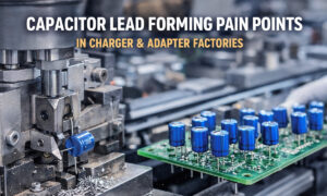
Role of the capacitor forming machine
A modern <a href=”/products/capacitor-forming-machine”>capacitor forming machine</a> can:
- Cut and bend radial electrolytic capacitor leads to a precise pitch, length, and stand-off height
- Limit mechanical force applied to the seal and can body, reducing micro-cracks and internal damage
- Ensure the same geometry for every board, which stabilizes thermal behavior and solder quality
Role of the lead forming machine
A lead forming machine is used for a broader range of through-hole components (film capacitors, disc ceramics, high-voltage capacitors, etc.) and:
- Shapes leads into L-bends, K-bends, and other forms required by the PCB layout
- Controls body height, tilt angle, and clearance to meet creepage and vibration specs
- Reduces variation that might otherwise create hotspots or stress concentrations
When you combine sound electrical design with consistent mechanical processing, the effective lifetime of your electrolytic capacitors becomes much closer to the theoretical lifetime you calculated.
5. Summary of the 5 Factors
The table below summarizes how each factor influences electrolytic capacitor lifetime and what you can do about it.
Table 2 – Key Lifetime Factors and Design Levers
| Factor | Direction of Influence on Lifetime | What You Can Control |
|---|---|---|
| 1. Core temperature | Every 10 °C decrease roughly doubles life | Thermal layout, airflow, distance from hot parts, capacitor series |
| 2. Ripple current & ESR | Higher ripple and ESR → more heating → shorter life | Select low-ESR series, parallel parts, verify ripple ratings |
| 3. Applied voltage vs rating | Higher stress near rating → faster aging | Voltage derating, margin for surges and mains tolerance |
| 4. Duty cycle & environment | High duty, vibration, humidity → accelerated aging | Choose appropriate series, add margin, use environmental protection |
| 5. Manufacturing & lead forming | Excessive mechanical stress or poor soldering → early failures | Use controlled forming, proper soldering, automatic inspection |
For a more complete view of how lead-forming equipment fits into your overall assembly strategy, you can read a dedicated lead formers buying guide. And if you’re still building your internal standards for component selection, pairing this article with an electronic component parameter guide will give your team a strong foundation.
6. Practical Lifetime Design Workflow
When designing a power supply or inverter, you can follow this workflow to ensure your electrolytic capacitors meet your lifetime targets:
- Define the target product life
- Example: 5 years at 24/7 industrial use, or 10 years at 8 hours/day for office equipment.
- Estimate core temperature
- Use thermal simulation, prototypes, or infrared measurements to determine capacitor core temperature at worst-case load and ambient.
- Remember: T_core ≈ T_ambient + ΔT_ripple.
- Apply the lifetime equation
- Use the 10 °C rule with the manufacturer’s load-life rating to get a first estimate.
- Add margin for environment and duty-cycle uncertainties.
- Choose appropriate series and rating
- Higher-temperature/higher-life series often cost more but can easily pay for themselves in reduced warranty risk.
- Consider whether a hybrid design (electrolytic + film) is needed for DC-link and high-ripple sections.
- Design for manufacturability and reliability
- Define clear standards for lead length, pitch, and stand-off height.
- Plan to use equipment such as a capacitor forming machine on radial electrolytics and a lead forming machine on larger film and high-voltage capacitors.
- Verify solder quality and mechanical robustness with vibration and thermal cycling tests.
7. Conclusion
Electrolytic capacitors will always be one of the weakest links in long-life power electronics — but they don’t have to be a guessing game.
If you:
- Understand the datasheet lifetime rating,
- Apply the 10 °C rule correctly,
- Control the five key factors (temperature, ripple, voltage stress, environment, and manufacturing quality),
you can design power supplies and inverters where the capacitors comfortably meet, or exceed, your product lifetime goals.
Combined with structured internal standards for component parameters and assembly processes — supported by tools like a well-tuned capacitor forming machine on the line — your electrolytic capacitors become an engineered, predictable part of system reliability, not an unpleasant surprise waiting to happen.