
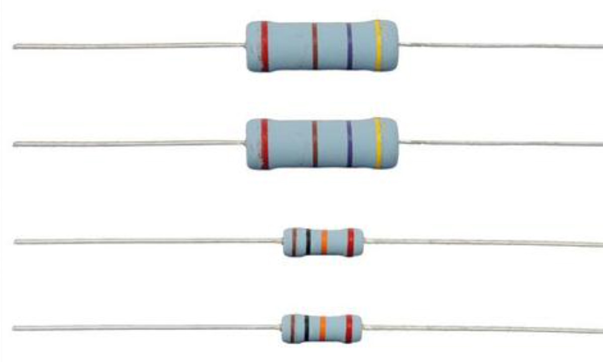
When you design a power supply, control board, or measurement circuit, resistors look like the simplest part on the BOM. But choosing between precision resistors and standard (general-purpose) resistors directly affects accuracy, noise, long-term drift, and even production cost.
This guide explains the practical differences between precision and ordinary resistors, shows how they impact real circuits, and gives you a structured way to choose the right type for each position in your design.
1. What Do We Mean by “Precision” vs “Standard” Resistor?
In practice, the industry usually distinguishes them by tolerance, temperature coefficient, and stability:
- Standard resistors (general-purpose):
- Tolerance: typically ±1% to ±5%
- Temperature coefficient (TCR): about ±100–300 ppm/°C
- Long-term drift: higher; less stable under load and temperature cycles
- Typical technology: thick-film SMD, carbon film, low-cost metal film
- Precision resistors:
- Tolerance: typically ±0.1% or better, often down to ±0.01%
- TCR: about ±5–25 ppm/°C (sometimes even lower)
- Long-term drift: much lower; specified over 1,000–10,000 hours
- Typical technology: metal film, thin-film SMD, foil resistors
1.1 Quick comparison table
| Feature | Standard Resistor | Precision Resistor |
|---|---|---|
| Common Tolerance | ±1–5% | ±0.1%, ±0.05%, ±0.01% |
| Typical TCR | 100–300 ppm/°C | 5–25 ppm/°C |
| Long-Term Stability | Moderate | High (specified low drift) |
| Price | Low | 3–10× higher (or more) |
| Typical Applications | LED current, pull-ups, bias | ADC references, gain setting, sensing |
Understanding these basics is easier if you already have a solid grip on resistor parameters and other passives; if not, it’s worth reviewing a complete electronic component parameter guide before you finalize your BOM.
2. Key Parameters That Drive the Choice
When you decide between precision and standard resistors, consider at least these parameters:
2.1 Resistance value & tolerance
- Resistance value is usually chosen from E-series (E6, E24, E96, etc.).
- Tolerance tells you how far the actual value may deviate from the nominal:
Example:
- 10 kΩ ±5% → actual value can be 9.5 kΩ to 10.5 kΩ
- 10 kΩ ±0.1% → actual value can be 9.99 kΩ to 10.01 kΩ
In gain-setting networks, voltage dividers, and current sense resistors, this tolerance can translate almost directly into output error.
2.2 Temperature coefficient of resistance (TCR)
TCR shows how much the resistance changes with temperature:
ΔR = R × TCR × ΔT
Assume a 10 kΩ resistor:
- Standard resistor: TCR = 200 ppm/°C
- Precision resistor: TCR = 10 ppm/°C
- Temperature range: 25 °C to 75 °C (ΔT = 50 °C)
Standard resistor drift:
- TCR = 200 ppm/°C = 0.0002/°C
- ΔR = 10,000 Ω × 0.0002 × 50 ≈ 100 Ω
- Relative change ≈ 1%
Precision resistor drift:
- TCR = 10 ppm/°C = 0.00001/°C
- ΔR = 10,000 Ω × 0.00001 × 50 ≈ 5 Ω
- Relative change ≈ 0.05%
If your circuit operates over a wide temperature range, this drift can dominate your accuracy budget.
2.3 Long-term stability & load life
Resistors drift over time due to:
- Continuous power dissipation (self-heating)
- Humidity and environmental stress
- Soldering and mechanical stress
Precision resistors usually specify drift after 1,000 or 10,000 hours at rated conditions, such as:
- Standard metal film: ±1% after 1,000 h at rated power
- Precision thin-film: ±0.05% or better over the same period
If you design industrial, medical, or instrumentation products that must stay calibrated for years, this drift is just as important as initial tolerance.
2.4 Noise & voltage coefficient
In high-gain, low-noise analog circuits:
- Resistor noise and voltage coefficient (change in resistance with applied voltage) can introduce errors and distortion.
- Precision metal-film, thin-film, or foil resistors are preferred because they have lower excess noise and better linearity than cheap carbon or thick-film parts.
2.5 Power rating, package, and thermal behavior
Don’t ignore basic mechanical and power constraints:
- Power rating (¼ W, ½ W, 1 W, etc.) must exceed your worst-case dissipation with margin.
- Package (SMD vs through-hole) impacts parasitics and assembly.
- For through-hole resistors, forming and trimming leads should be controlled to avoid cracking the coating or stressing the joint; in volume production, this is typically done using dedicated electronic component lead forming machines rather than manual tools.
3. Where You Must Use Precision Resistors
You don’t need precision parts everywhere—only at positions where resistor error directly limits system performance. Typical cases:
3.1 Precision gain-setting in op-amp circuits
Consider a non-inverting amplifier:
Gain = 1 + R2 / R1
If R1 = R2 = 10 kΩ, nominal gain is 2. Now compare two scenarios:
- Standard resistors ±1%
- Worst-case R1 = 9.9 kΩ, R2 = 10.1 kΩ → Gain ≈ 2.02 (+1%)
- Or R1 = 10.1 kΩ, R2 = 9.9 kΩ → Gain ≈ 1.98 (−1%)
- Precision resistors ±0.1%
- Worst-case gain error drops to about ±0.1% instead of ±1%.
For sensor conditioning, instrumentation amplifiers, and reference scaling, 1% error might be unacceptable, forcing you to use precision parts or matched resistor networks.
3.2 ADC reference dividers and feedback
In systems where:
- You use a resistor divider to scale a high voltage down to the ADC input range, or
- You set the feedback ratio of a switching power supply,
resistor tolerance and TCR directly impact:
- ADC reading accuracy
- Output voltage regulation
- Line/load regulation performance
A ±5% resistor can easily move your ADC full-scale point or regulator output outside spec; here, ±0.1% or ±0.5% is often required.
3.3 Current sensing and power monitoring
Current sense resistors (shunts) must be controlled accurately because any error in R translates into error in measured current:
I = V / R
Example:
- Sense resistor: 10 mΩ
- Tolerance: ±5% → 9.5–10.5 mΩ
- Measuring a 10 A current → nominal Vsense = 0.1 V
Worst-case interpretation:
- At 9.5 mΩ, measured current appears lower than actual
- At 10.5 mΩ, measured current appears higher than actual
Using a ±1% or ±0.5% precision shunt dramatically improves current measurement accuracy, which is critical for:
- Battery management systems
- Motor control
- High-efficiency power supplies
4. Where Standard Resistors Are More Than Enough
Paying for precision where it isn’t needed just inflates your BOM. In many positions, standard 1–5% resistors are perfectly fine:
4.1 LED current limiting
For an indicator LED:
- Target current: 10 mA
- A ±5% variation changes it to roughly 9.5–10.5 mA
Result: brightness variation is hardly noticeable to the end user. Using a ±0.1% resistor here delivers almost no practical benefit.
4.2 Pull-up / pull-down resistors
For logic inputs:
- As long as the resistor is within a reasonable range (e.g., 4.7 kΩ, 10 kΩ, 47 kΩ),
- Voltage levels remain clearly recognized as HIGH or LOW.
Whether the actual value is 9.7 kΩ or 10.3 kΩ makes almost no difference to logic thresholds, so a standard 1–5% part is more than adequate.
4.3 Simple biasing and timing when tolerances are already loose
In some analog circuits (e.g., audio tone controls, crude RC delays, simple transistor biasing):
- The system itself is not tightly specified.
- Component tolerances of ±10% may be perfectly acceptable.
Here, standard resistors keep cost under control without impacting user-visible performance.
5. Data-Driven Comparison: Precision vs Standard in Real Circuits
To make the trade-off clear, consider these simplified examples:
5.1 Voltage divider for reference scaling
Target: divide 5 V down to 2.5 V.
Use R1 = R2 = 10 kΩ (upper and lower resistors).
- Ideal output: 2.5 V
Case 1: Standard ±1% resistors
- Worst-case high: R1 = 9.9 kΩ, R2 = 10.1 kΩ
- Vout ≈ 5 V × 10.1 / (9.9 + 10.1) ≈ 2.525 V (+1%)
- Worst-case low: R1 = 10.1 kΩ, R2 = 9.9 kΩ
- Vout ≈ 5 V × 9.9 / (10.1 + 9.9) ≈ 2.475 V (−1%)
Case 2: Precision ±0.1% resistors
- Worst-case Vout error drops to roughly ±0.1%, or about ±2.5 mV.
If your ADC and system spec allow only ±0.5% total error, the ±1% divider alone already eats the whole budget; precision parts become mandatory.
5.2 Thermal drift across temperature
Using the TCR example from earlier:
| Parameter | Standard Resistor | Precision Resistor |
|---|---|---|
| Nominal Resistance | 10 kΩ | 10 kΩ |
| TCR | 200 ppm/°C | 10 ppm/°C |
| Temperature Change (ΔT) | 50 °C | 50 °C |
| Resistance Change (ΔR) | ≈ 100 Ω | ≈ 5 Ω |
| Relative Change | ≈ 1% | ≈ 0.05% |
In a system that must stay calibrated from −20 °C to +60 °C, that extra 0.95% error might force costly field recalibration—or early product complaints.
6. A Practical Selection Workflow
When you face a new design or need to review an existing one, use this simple decision workflow:
- Define the function of each resistor position
- Is it functional but non-critical (LED, pull-up), or measurement/feedback-critical (sense resistor, reference divider, gain setting)?
- Allocate an error budget
- How much total error can the system tolerate (e.g., ±1%, ±2%)?
- What portion of that can come from resistor tolerance and drift?
- Choose tolerance and TCR accordingly
- If resistor error must stay below ±0.5% over life and temperature, precision is required.
- If ±5–10% is acceptable, standard resistors are fine.
- Consider environment and lifetime
- Wide temperature range, 24/7 operation, or safety-critical use all favor precision and better stability.
- Balance cost vs value
- Use precision resistors only where they materially improve end-product performance or reduce calibration cost.
- Everywhere else, standard resistors minimize BOM cost.
For a deeper dive on how to turn these steps into a repeatable engineering/purchasing process, a more general electronic component parameter selection guide can help you extend the same thinking to capacitors, inductors, diodes, and ICs as well.
7. Summary: How to Decide in One Glance
You should choose precision resistors when:
- The resistor directly affects measurement accuracy or reference values
- You need tight matching between resistor pairs or networks
- The system sees wide temperature swings or long lifetimes
- Calibration costs are high or impractical
You can safely use standard resistors when:
- The function is non-critical (indicators, pull-ups, simple biasing)
- The system’s own tolerance is loose, and users don’t notice small variations
- You’re optimizing for cost and volume without hurting real-world performance
The right strategy is almost always mixed: precision where it matters, standard where it doesn’t. That way you get robust, accurate designs without blowing up your BOM—exactly what good engineering and smart procurement aim for.