Choosing the right resistor type is not just about hitting a resistance value. Noise, power, temperature, size, and cost all change dramatically when you switch from carbon film to metal film, metal oxide, cement, wirewound, or SMD resistors. Pick the wrong one in a power supply or feedback loop and you’ll see drift, overheating, or audible noise creeping into the design.
Below is a practical, scenario-driven guide to where each common resistor type really fits in modern electronics production.
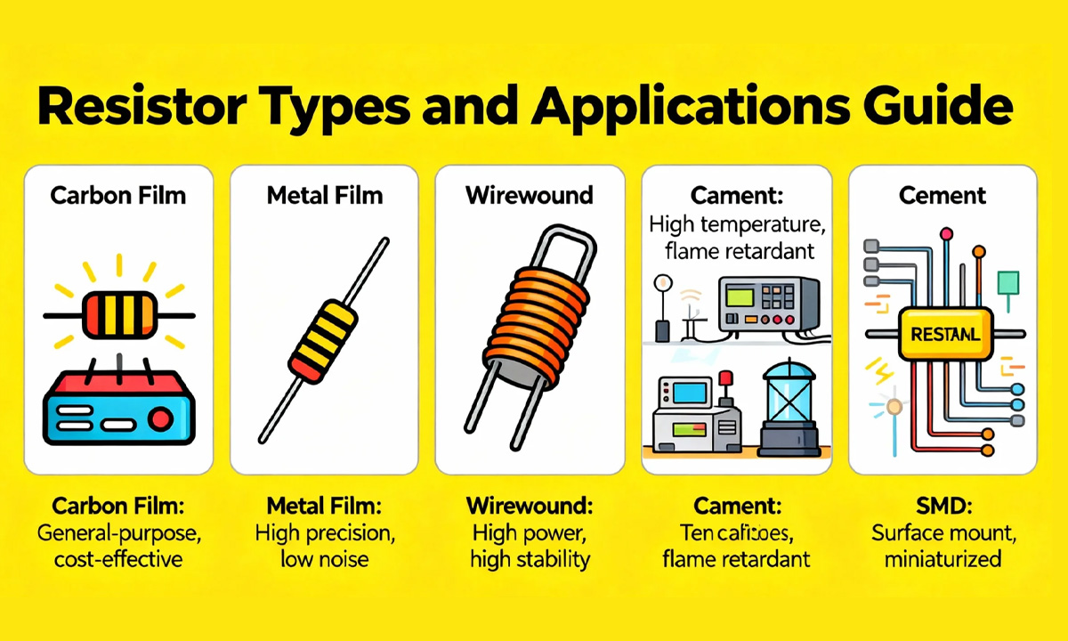
Quick Comparison: Which Resistor for Which Job?
| Resistor type | Typical power range | Typical tolerance | Temperature behavior | Key strengths | Typical application scenarios |
|---|---|---|---|---|---|
| Carbon film (through-hole) | 0.125–5 W at 70 °C | ±2–20 % (±5 % most common) | Several hundred ppm/°C, often negative; poor TCR vs film types | Very low cost, wide resistance range | Cost-sensitive general-purpose circuits, pull-ups, LED current limiting where noise and precision are not critical |
| Metal film | Up to ~1–2 W (typical signal parts) | ±0.1–1 % | ~10–100 ppm/°C, very stable | Low noise, tight tolerance, stable over time | Precision analog, op-amp feedback, audio, filters, reference dividers |
| Metal oxide film (often called “resistor film” in factories) | Above 1 W common; higher voltage and surge capability than carbon/metal film | Typically ±2–5 % | Can operate up to ~450 °C, higher surge and overload capacity | High endurance in hot, harsh environments | Power supplies, snubber and surge resistors, automotive, industrial power |
| Cement resistor (power resistor) | 2, 3, 5, 10 W and above | ±5–10 % | Designed to run hot; ceramic body with good heat dissipation | High power, shock- and moisture-resistant, low cost per watt | Braking/load resistors, inrush limiters, bleeder resistors in power supplies, audio dummy loads |
| Wirewound resistor | 1–50 W typical; special models much higher | ±1–5 % (precision types lower) | Very low TCR, excellent thermal stability; but inductive at high frequency | Very high power handling, precise, robust | Motor drives, braking resistors, dummy loads, current sense, high-power resistive dividers |
| SMD / chip (thick-film) resistor | ~0.03–2 W at 70 °C, depending on size | ±0.5 %, ±1 %, ±5 % | Typical TCR ±100–400 ppm/°C | Small size, low cost, automated assembly, non-inductive | High-density PCBs, consumer electronics, telecom, automotive ECUs, anything fully SMT |
Analog Devices’ own applications engineers summarize it well: metal film parts are the go-to choice when you need initial accuracy, a low temperature coefficient, and lower noise in bridge circuits, oscillators, and active filters.
Carbon Film Resistors: Low-Cost Generalists for Non-Critical Nodes
Best for:
Cost-sensitive designs, pull-ups, LED current limiting, non-critical dividers.
Carbon film resistors are made by depositing a carbon layer on a ceramic rod, then spiral-cutting it to reach the target resistance. Typical power ratings sit between 0.125 W and 5 W at 70 °C, with resistance values from 1 Ω up to around 10 MΩ.
Key characteristics:
- Tolerance: Commonly ±5–10 %, with ±2 % available for “better” grades.
- Temperature coefficient: Often several hundred ppm/°C and can be strongly negative, so resistance drifts noticeably with temperature.
- Noise: Lower noise than old carbon composition parts, but noisier and less stable than metal film.
Use carbon film when:
- You’re building cost-driven consumer electronics where ±5 % is fine (simple LED indicators, relay coils, pull-ups/pull-downs).
- The node is not in a precision path: no tight gain requirement, no ultra-low drift spec.
- Voltage and temperature are moderate; for harsh or hot environments, metal oxide film is safer.
Avoid carbon film in tight tolerance feedback networks, reference dividers, or low-noise audio stages. There, metal film or SMD thin/thick film will give a much more stable result.
Metal Film Resistors: Precision and Low Noise for Signal Paths
Best for:
Precision gain-setting, audio, reference and sensor circuits.
Metal film resistors use a thin metal layer (often Nichrome) on a ceramic core. Compared with carbon types, they offer:
- Tight tolerance: 0.1–1 % is typical in standard series.
- Low TCR: Around 10–100 ppm/°C, which greatly reduces drift over temperature.
- Lower noise: Multiple studies and vendor notes show metal film exhibits less thermal and flicker noise than carbon film at the same value.
Because of this, vendors and application notes consistently recommend metal film in:
- Op-amp feedback networks and instrumentation amplifiers
- RC filters, oscillators, and precision timing networks
- Audio signal paths, where resistor noise shows up as hiss
- High-resolution ADC/DAC reference and divider networks
In many power-supply factories, it’s common to see a mix: low-cost carbon film parts on non-critical nodes, and 1 % metal film on feedback, sense, and protection circuits where specs are tight.
If you need higher power in the same circuit (for example, a precision resistor that still has to burn 1–2 W), it’s often better to go to metal oxide film or a wirewound part instead of trying to push a small metal film beyond its comfort zone.
Metal Oxide Film Resistors (“Resistor Film”): High-Endurance Workhorses
Best for:
Hot, harsh, high-energy environments (SMPS, snubbers, automotive, industrial).
Metal oxide film resistors are also axial parts, but the resistive layer is a metal oxide (commonly tin oxide) on a ceramic rod. They’re designed for high endurance and harsh conditions:
- Can operate at temperatures up to ~450 °C, significantly higher than carbon or metal film.
- Offer better power rating, voltage rating, surge capacity, and overload capability compared with carbon film.
- Price is still very close to regular film parts, so they’re widely used when reliability matters.
Because of this, designers often pick metal oxide film for:
- Primary-side resistors in SMPS (inrush limiters, startup and bleeder resistors).
- Snubber and surge resistors across MOSFETs, bridge rectifiers, and transformers.
- Automotive and industrial control boards, where ambient temperature and transients are more severe.
- High-voltage dividers, where creepage, insulation, and long-term stability under load are important.
Noise and precision are not quite as good as high-grade metal film, but for power and endurance-critical applications, metal oxide film is usually the safer choice.
Cement Resistors: Classic Power Bricks for Braking and Bleeder Loads
Best for:
High power, low-to-medium precision jobs where the resistor will run hot.
“Cement resistor” usually refers to a power wirewound or film resistor inside a ceramic (cement-like) housing. Typical ratings are 2 W, 3 W, 5 W, 10 W and higher, with good shock, moisture, and heat resistance.
They are widely used in:
- Power adapters and TV power boards – as bleeder or drop resistors.
- Audio equipment – as load/dummy resistors for testing amplifiers.
- Motor controllers and brake choppers – dissipating energy during deceleration.
- Automotive and industrial equipment – where vibration and temperature swings are severe.
Use cement resistors when:
- You need a cheap, robust way to burn power.
- Size is acceptable and inductance is not a big issue (for brake resistors, soft-start, or discharge resistors, small inductance is usually fine).
- You want flame-resistant construction and easy mounting to metal chassis or heatsinks.
If the power is extremely high or switching frequencies are very high, you may step up to dedicated aluminum-cased wirewound or thick-film power resistors instead.
Wirewound Resistors: High-Power and High Accuracy, With an Inductive Side Effect
Best for:
High-power loads, current sense, and precise low-value resistors.
Wirewound resistors are made by winding a resistive wire (often Nichrome or similar alloys) on a ceramic core. They stand out for:
- Very high power ratings – power wirewounds commonly fall in the 25–50 W range for single devices, and higher with finned aluminum housings.
- Excellent thermal stability and low TCR; some wirewounds can reach 10 ppm/K class performance.
- Long-term stability under continuous heavy load.
Because the current flows through a coil, wirewounds have inductance, which can distort high-frequency signals or upset fast switching edges. Non-inductive versions (Ayrton–Perry windings, specialized construction) exist, but they’re more specialized.
Typical use cases:
- Dynamic braking and load banks in motor drives and cranes.
- High-power dummy loads for RF amplifiers and power stages.
- Low-value current-sense resistors in high-current power supplies or battery testers.
- High-precision standards and dividers, where very low TCR and long-term stability are more important than physical size.
If your circuit is sensitive to inductance (RF, fast switching, snubbers on high-dv/dt nodes), consider metal film, metal oxide film, or SMD thick-film instead.
SMD (Chip) Resistors: Default Choice for Modern High-Density PCBs
Best for:
Any SMT production where density, cost, and automation dominate.
Thick-film chip resistors are now the standard in most electronics. According to manufacturers such as Bourns and ROHM, modern thick-film chip series:
- Cover power ratings roughly from 0.03 W to 2 W at 70 °C, depending on package size.
- Offer resistance ranges from a few tens of milliohms up to tens of megaohms.
- Provide tolerances of 0.5 %, 1 %, and 5 %, with TCR options around ±100 to ±400 ppm/°C.
- Are inherently non-inductive due to their film geometry, which is helpful at higher frequencies.
Typical applications:
- Consumer electronics and mobile devices – everything from button pull-ups to precision sensor scaling.
- Telecom and networking boards, where density and high-frequency behavior matter.
- Automotive ECUs, often using AEC-Q200 qualified chip resistors.
- Mixed-signal and RF boards, which benefit from the compact, non-inductive structure.
Design tips:
- Use 1 % parts for signal gains, reference dividers, and sense paths.
- Use 5 % parts for logic pull-ups, configuration, and non-critical biasing.
- Watch the power at 70 °C and derating curves—small 0402 or 0201 parts heat up fast if you treat them like 1/4-W through-hole resistors.
From Component Choice to Manufacturing: Matching Resistor Type and Production Equipment
In real factories, resistor selection is tied closely to how the components will be processed:
- Axial carbon film, metal film, and metal oxide resistors used on through-hole boards usually need consistent lead length and forming for vertical or horizontal mounting.
- Power cement and wirewound resistors may be bolted to heatsinks or mounted with special brackets, but still require reliable lead processing when they are leaded parts.
- Moving to SMD resistors shifts the problem to stencil design and reflow profiles, but dramatically simplifies assembly and automated testing.
If your line still handles large volumes of through-hole resistors, precise forming is critical for insertion quality and solder joint reliability. For a structured overview of the machines typically used on axial parts, you can reference this guide on resistor lead cutting and forming equipment, which walks through vertical, horizontal, and tape-mounted resistor formers in a production environment.
Factories that process both carbon film and metal film axial resistors in multiple orientations often standardize on flexible equipment. An integrated system such as the FL-612 High-Precision Resistor Horizontal and Vertical Integrated Forming Machine can switch between horizontal and vertical forming via tooling changes, keeping the same machine compatible with different resistor types and product lines.
How to Choose Quickly by Scenario
When you’re under time pressure, you can simplify the decision to a few rules of thumb:
- Low-cost, non-critical node:
Use carbon film (through-hole) or 5 % thick-film SMD. - Precision analog, audio, low noise:
Use 1 % or better metal film (through-hole) or 0.5–1 % SMD chips. - Hot, harsh, or surge-heavy environments (SMPS, automotive power):
Use metal oxide film or cement resistors; consider wirewound for very high energy. - High-power loads, braking, dummy loads, current sense:
Use wirewound or cement resistors; check inductance requirements for high-frequency work. - High-density or fully automated SMT line:
Default to SMD thick-film, upgrading to thin-film SMD where ultra-low TCR is required.
By mapping each resistor type to its natural “comfort zone” — precision, power, endurance, or density — you can keep both circuit performance and manufacturing efficiency under control, instead of fighting field failures or production headaches later.