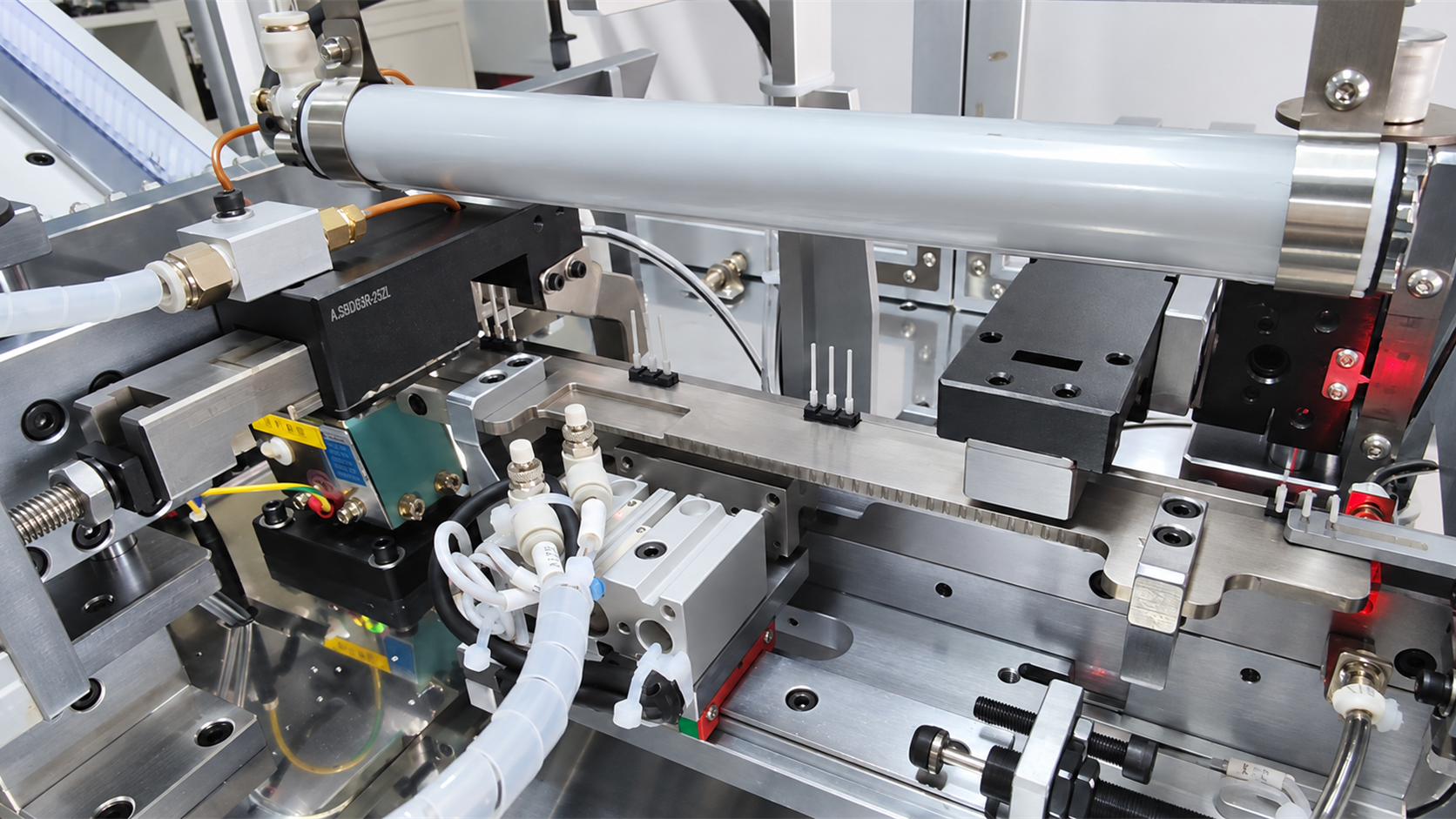
TO-220 lead forming is the controlled trimming and bending of a through-hole power semiconductor’s leads to match a specified PCB hole pattern, mounting height, or heatsink assembly. Common operations include lead cutting, 90-degree bending, offset forming, and lead spreading. A reliable process must achieve the required dimensions without cracking the lead plating or transferring excessive mechanical stress to the package.
When selecting TO-220 lead forming equipment, engineers should confirm the incoming packaging format, lead dimensions and tolerances, required forming profile, production rate, changeover frequency, and inspection method. Manual tooling is generally suitable for prototypes and low-volume production, while semi-automatic or automatic equipment provides better consistency for higher-volume assembly.
This guide covers common TO-220 components and packaging formats, lead-forming shapes, dimensional requirements, and equipment options for PCB insertion, horizontal mounting, and heatsink assembly.
What Is TO-220 Lead Forming?
TO-220 is a family of through-hole semiconductor packages commonly associated with power devices. The package typically has a molded body, a mounting tab or thermally conductive surface, and multiple leads. However, “TO-220” does not define one universal set of dimensions. Full-pack, isolated, long-lead, short-lead, and manufacturer-specific variants may differ in body thickness, tab construction, lead width, lead thickness, and lead length.
The term TO-220 lead forming refers to changing the geometry of the finished component leads before installation. Depending on the assembly, the process may include:
- trimming all leads to a controlled length;
- bending the leads to 90 degrees for horizontal mounting;
- creating an offset or kink to establish PCB spacing;
- spreading or reducing the lead pitch;
- offsetting one lead relative to the other leads;
- producing unequal finished lead lengths; or
- combining cutting and forming in one tooling cycle.
Lead forming should not be confused with semiconductor back-end trim-and-form processing. Semiconductor trim-and-form equipment separates and forms devices from a leadframe during package manufacturing. The equipment discussed here processes already packaged components before PCB or mechanical assembly.
Which TO-220 Devices May Require Lead Forming?
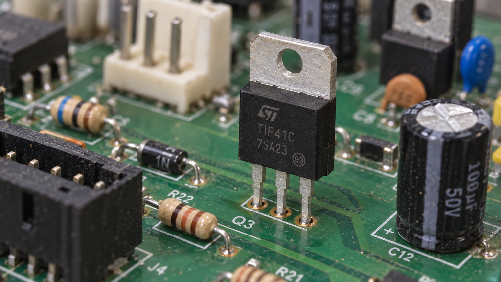
Although the package name begins with “transistor outline,” TO-220 devices are not limited to bipolar transistors. A TO-220 lead forming machine may be used for several types of discrete power semiconductors, provided the tooling and handling method match the actual package.
| Device category | Typical assembly consideration | Information to verify before forming |
|---|---|---|
| Power MOSFET | PCB insertion, heatsink alignment, and electrostatic-discharge controls | Exact package suffix, lead arrangement, tab style, and handling requirements |
| IGBT | Power-conversion assembly and heatsink mounting | Three-lead or four-lead configuration, lead thickness, and required offsets |
| Bipolar power transistor | Amplifier, power-supply, and switching assemblies | Pin assignment, finished pitch, and installation orientation |
| SCR or triac | Power-control PCB and thermal assembly | Package drawing, creepage requirements, and mounting direction |
| Rectifier or power diode | Power-supply and protection circuits | Number of leads, polarity orientation, and finished geometry |
| Voltage regulator or power IC | PCB mounting with or without a heatsink | Lead count, package variant, standoff, and thermal interface |
A machine specification should therefore identify the exact manufacturer and part number instead of stating only “TO-220.” The package drawing for the purchased component is the controlling dimensional reference.
Why Are TO-220 Leads Formed Before Assembly?
The original straight-lead configuration is suitable for many vertical through-hole applications, but it does not meet every PCB or mechanical layout. Controlled preforming may be required for the following reasons:
- Horizontal mounting: The package must lie parallel to the PCB or align with a chassis-mounted heatsink.
- PCB hole alignment: The required hole pitch differs from the original lead pitch.
- Stand-off control: A defined distance is required between the package body and the PCB.
- Mechanical stress relief: An offset or controlled bend may accommodate assembly movement or thermal expansion.
- Heatsink positioning: The mounting surface and hole must align without forcing the leads or package body.
- Automated insertion: Consistent lead geometry improves presentation to fixtures, insertion equipment, and downstream assembly stations.
The finished geometry should be defined from assembly datums, not from a visually acceptable sample alone. A sample can support feasibility evaluation, but an approved drawing is required to control production and inspection.
Common TO-220 Lead Forming Configurations
Straight Lead Trimming
Straight trimming reduces the leads to a specified finished length without intentionally changing their direction. The process must control cut length, burr condition, lead deformation, and the position of the component during cutting.
90-Degree Lead Bending
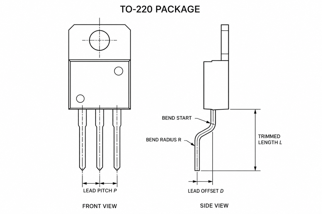
A 90-degree bend is commonly used when the package is mounted horizontally or attached to a heatsink positioned relative to the PCB. The specification must define the bend direction, bend-start location, inside bend radius, final mounting height, and reference surface.
Offset or Kink Forming
An offset consists of two controlled bends that move part of the lead to a parallel but displaced position. It may establish stand-off, change the insertion location, or create clearance around another part of the assembly. Both the offset distance and the distance between bend points must be specified.
Lead Pitch Adjustment
Lead spreading or inward forming changes the center-to-center spacing of the leads. This operation requires symmetrical support and accurate component location because pitch correction can introduce twist, nonparallel leads, or unequal insertion positions.
Center-Lead Offset or Unequal Lead Lengths
Some assemblies require the center lead to be offset, isolated, or cut to a different length. The tooling must control each lead without allowing adjacent leads to interfere. Pin identification and component orientation become critical when the finished geometry is not symmetrical.
Critical Dimensions for a TO-220 Forming Drawing
A tooling supplier cannot define a stable process from a general description such as “bend the leads 90 degrees.” The drawing must state how every finished dimension is measured and which features serve as datums.
| Drawing item | What must be defined | Why it matters |
|---|---|---|
| Package datum | Body face, body bottom, tab surface, or another controlled reference | Prevents different inspection methods from producing different results |
| Bend-start distance | Distance from the package body or specified datum to the first bend | Controls package clearance and reduces stress near the lead entry |
| Inside bend radius | Radius at each forming location | Affects lead strain, plating condition, and repeatability |
| Bend angle | Nominal angle and tolerance | Controls final alignment with the PCB or heatsink |
| Finished lead length | Length from the selected datum to the cut end | Affects insertion depth, protrusion, and downstream handling |
| Lead pitch | Center-to-center spacing after forming | Determines alignment with PCB holes or fixtures |
| Offset | Horizontal or vertical displacement after forming | Defines mounting position and stand-off |
| Tip alignment | Allowable deviation among finished lead ends | Affects simultaneous PCB insertion |
| Burr direction and limit | Permitted burr orientation and acceptance method | Influences insertion, handling, and inspection |
| Surface condition | Acceptance criteria for cracks, scratches, and plating damage | Protects solderability and product reliability |
Package-specific guidance is essential. For example, Infineon’s recommendations for board assembly of TO packages state that, for the package constructions covered by that document, leads should not be bent directly at the package edge and describe a minimum distance to the first bend. That value must not be treated as a universal rule for every TO-220 device. The selected component manufacturer’s current drawing and assembly instructions remain authoritative.
A Controlled TO-220 Lead Forming Process
A reliable process separates component presentation, location, mechanical support, cutting, forming, and inspection. Combining these functions without defined datums can create variation that appears to be a tooling problem but actually originates in feeding or positioning.
1. Verify the Incoming Component
Confirm the manufacturer, part number, package suffix, lot condition, incoming lead geometry, and packaging method. Measure representative samples before designing the tooling. Nominal package names alone are insufficient because different sources may supply dimensional variants under the same general package family.
2. Feed and Orient the Component
Components may be loaded manually or supplied from tubes, trays, or a bulk-feeding system. The process must maintain the required front-to-back and pin orientation. If the final lead form is asymmetrical, an incorrectly oriented component may pass through the machine but become unusable in assembly.
3. Locate and Support the Leads
The package and leads must be located from repeatable surfaces. Lead support between the package body and the forming point helps prevent bending force from being transferred into the package. Taiwan Semiconductor’s TO-220 mounting and bending guidance similarly emphasizes holding the leads during forming rather than allowing the package interface to absorb the load.
4. Cut and Form in a Defined Sequence
Cutting may occur before, during, or after forming, depending on the required geometry and tooling design. The sequence affects part support, cut-length control, burr orientation, and the risk of deforming a finished bend. The chosen sequence should be validated with actual production components.
5. Release and Transfer Without Secondary Deformation
Finished parts must leave the tooling without catching, dropping onto vulnerable leads, or being compressed in the collection container. A stable forming operation can still produce poor outgoing quality if unloading and part accumulation are not controlled.
6. Inspect Against the Approved Drawing
First-article inspection should confirm every critical dimension and surface requirement. Production controls may then use a combination of dimensional measurement, go/no-go fixtures, vision inspection, and scheduled sampling according to the application risk.
Common Quality Risks and Corrective Actions
Improper TO-220 lead bending can affect both mechanical fit and component reliability. Potential failure modes include plating cracks, lead deformation, package damage, dimensional drift, and incorrect orientation. The following table provides a structured starting point for troubleshooting; it does not replace failure analysis on the actual component.
| Observed condition | Possible process cause | Verification method | Corrective direction |
|---|---|---|---|
| Cracking or flaking at the bend | Bend radius too small, unsupported lead, unsuitable bend location, or repeated bending | Magnified visual inspection and review against the component manufacturer’s guidance | Increase the qualified radius, revise lead support, or relocate the bend |
| Package cracking or internal damage concern | Forming force transferred toward the lead-to-body interface | Inspect the package, review the clamping location, and perform the customer’s required electrical or reliability test | Clamp the lead before the bend point and reduce force transferred to the package |
| Unequal finished lead length | Variable component seating, cutting clearance, tool wear, or lead movement | Measure from the specified datum and review the locating sequence | Improve part location, cutting support, and preventive maintenance |
| Lead pitch outside tolerance | Part mislocation, asymmetrical tool contact, or springback variation | Use an optical system or qualified fixture to measure all leads | Correct the locating surfaces, tooling alignment, or compensation |
| Twisted or nonparallel leads | Uneven forming force or lateral movement during the stroke | Inspect from multiple directions and check tooling alignment | Improve lateral support and balance the forming action |
| Excessive burr | Worn cutting edges, incorrect clearance, or unstable lead support | Inspect the cut face under magnification | Service the cutter and verify cutting clearance |
| Intermittent dimensional drift | Feeding variation, debris, loose tooling, temperature effects, or progressive wear | Plot measurements by time and compare them with machine and maintenance records | Isolate the source before adjusting nominal tooling dimensions |
| Wrong bend direction | Incorrect component orientation or insufficient error proofing | Verify front/back and pin identification before the forming station | Add mechanical poka-yoke, orientation sensing, or fixture control |
For assemblies governed by IPC requirements, the applicable revision and product class should be specified by the customer or contract. IPC’s standards revision table lists the current revisions of J-STD-001 and IPC-A-610. These standards address soldered assembly requirements and acceptance criteria; they do not replace the device manufacturer’s package limits or the customer’s finished-part drawing.
Manual, Tube-Fed, Tray-Fed, or Bulk-Fed Processing?
The best feeding method is determined by incoming packaging, production volume, component sensitivity, and product mix. It should not be selected from output targets alone.
| Feeding method | Best suited to | Engineering advantages | Points to evaluate |
|---|---|---|---|
| Manual loading | Low volume, prototypes, and frequent product changes | Simple setup and flexible handling | Operator dependence, orientation control, ergonomics, and realistic cycle time |
| Tube-fed loading | Consistent production of tube-packaged devices | Orderly presentation and reduced orientation work | Tube dimensions, device movement, changeover, empty-tube handling, and buffer capacity |
| Tray-fed loading | Protected or high-value components supplied in trays | Controlled component position and reduced surface contact | Tray standard, pick-and-place method, pitch variation, and return-tray handling |
| Bulk or vibratory-bowl feeding | Higher-volume loose components with stable geometry | Continuous automatic supply | Part-on-part contact, orientation reliability, noise, jamming, package variation, and changeover complexity |
A purchasing specification should state whether production quantities are quoted as components per hour, cycles per minute, or accepted parts per hour. These values are not interchangeable. Net output also depends on loading, inspection, reject handling, replenishment, and changeover losses.
Tooling and Changeover Considerations
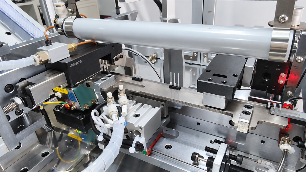
TO-220 forming tooling usually includes locating features, lead supports, clamps, forming punches or slides, cutters, and part-release features. A dedicated die may be required when package dimensions, lead thickness, or finished geometry differ. A machine that can process several package types does not necessarily use one universal tool for all of them.
Engineering and purchasing teams should evaluate:
- which package features are used as datums;
- whether the leads are clamped before cutting and bending;
- which tooling elements are product-specific;
- how tool alignment is established after replacement;
- whether recipes or mechanical stops control dimensions;
- how long a verified product change takes;
- which wear parts require scheduled replacement;
- how cut debris is contained and removed; and
- which gauges or master samples are supplied with the tooling.
Inspection and Process Validation
Inspection should be planned before tooling approval. If a dimension cannot be measured consistently, it cannot be controlled reliably in production.
| Control stage | Recommended verification | Record to retain |
|---|---|---|
| Incoming component review | Part number, package suffix, lead condition, and representative dimensions | Incoming inspection record and supplier drawing revision |
| Tool trial | All critical dimensions, surface condition, orientation, and downstream fit | Trial report with measured samples and photographs |
| First-article approval | Full drawing inspection using agreed methods | First-article inspection report and approved sample |
| Routine production | Defined sampling frequency or 100% checks for selected characteristics | Inspection log, reject count, and corrective-action record |
| After changeover or maintenance | Recheck critical dimensions and machine setup | Setup verification or restart approval |
| Pre-shipment machine acceptance | Run customer components under agreed conditions | FAT report, sample set, machine settings, and acceptance results |
Potential inspection tools include an optical comparator, calibrated vision system, height gauge, dimensional fixture, and go/no-go insertion fixture. The method should be matched to the tolerance and datum scheme. Contact measurement must not deform the leads or create a false result.
How to Select a TO-220 Lead Forming Machine
A suitable machine is one that can repeatedly produce the approved component geometry within the required production system. The following questions help separate essential requirements from optional automation.
| Evaluation area | Questions for the supplier |
|---|---|
| Component range | Which exact package variants and lead counts have been evaluated? Is separate tooling required for each part number? |
| Forming capability | Can the machine perform the required cutting, angle, offset, pitch, and unequal-length operations in the specified sequence? |
| Stress control | Where are the leads supported and clamped relative to the package body and bend point? |
| Feeding | Does the system match the customer’s actual tubes, trays, or bulk components? How is orientation verified? |
| Output | Is output stated as machine cycles or accepted components under continuous operating conditions? |
| Changeover | Which parts must be replaced or adjusted, and how is the first part verified after changeover? |
| Quality control | Which dimensions can be monitored in-process, and how are nonconforming parts handled? |
| Maintenance | What are the cutter, die, guide, and clamp maintenance intervals? Which spare parts are recommended? |
| Integration | Must the machine communicate with PCB insertion, heatsink assembly, screw fastening, or a traceability system? |
| Acceptance | Will FAT use the customer’s actual components, approved drawing, output target, and inspection method? |
Information Required for Technical Evaluation
Supplying complete project information reduces uncertainty in tooling design, quotation, and trial preparation. At minimum, provide the following data.
| Required information | Preferred format | Purpose |
|---|---|---|
| Manufacturer and component part number | Purchasing specification or approved vendor list | Identifies the exact device and package suffix |
| Original package drawing | Current manufacturer PDF or controlled drawing | Defines incoming dimensions and package limits |
| Actual component samples | Production-representative parts from approved suppliers | Supports feeding, tooling, and forming trials |
| Finished-part drawing | Dimensioned 2D drawing with datums and tolerances | Defines the required output |
| Incoming packaging | Tube, tray, bag, or reel specification with samples | Determines the feeding concept |
| Production requirement | Required accepted parts per hour and shift pattern | Supports automation and buffer sizing |
| Product mix | Part-number list and forecast volume by model | Determines tooling quantity and changeover strategy |
| Quality and traceability requirement | Inspection plan, customer standard, and data requirement | Defines sensors, vision, gauges, and records |
| Downstream assembly information | PCB, fixture, or heatsink drawing and process sequence | Verifies fit and integration constraints |
| Plant requirements | Power, air, safety, language, and communication standards | Defines the machine configuration and compliance scope |
TO-220 Lead Forming Machine Options
Flourishe currently offers several machines for transistor and power-device lead processing. The models are not interchangeable. They are intended for different component sizes, incoming packaging methods, production volumes, and forming requirements.
FL-951 Power Crystal Forming Machine
The FL-951 Power Crystal Forming Machine is designed for lead cutting and forming of power transistors, IGBTs, and similar power devices.
Suitable for:
- TO-220 and similar power packages
- Relatively stable forming shapes
- Medium- to high-volume production
- Cutting and forming in a compact machine
Advantages:
- Higher nominal processing speed
- Compact equipment structure
- Suitable for standard power-device forming
- Custom tooling can be designed for the required shape
Limitations:
- Tooling is still component- and shape-specific
- Product changes require tooling or setup adjustment
- Actual net output depends on loading and collection
- Not the best option when multiple forming shapes must be changed frequently
FL-952 Pneumatic Power Crystal Forming Machine
The FL-952 Pneumatic Power Crystal Forming Machine is suitable for cutting and forming tube-type power devices, including IGBTs and power transistors.
Suitable for:
- Tube-packaged TO-220 components
- Small and medium production batches
- Projects with customized forming shapes
- Applications where flexible tooling is more important than full automation
Advantages:
- Pneumatic forming provides stable operating force
- Suitable for cutting and bending thicker power-device leads
- Tooling can be customized for different lead shapes
- Simpler structure than a fully automatic bowl-fed machine
- Easier to use for sampling and new-product introduction
Limitations:
- Requires a stable compressed-air supply
- Output depends more heavily on the loading method
- More operator involvement may be required
- Less suitable for large-volume bulk components requiring unattended feeding
FL-955 Automatic Transistor Lead Forming Machine
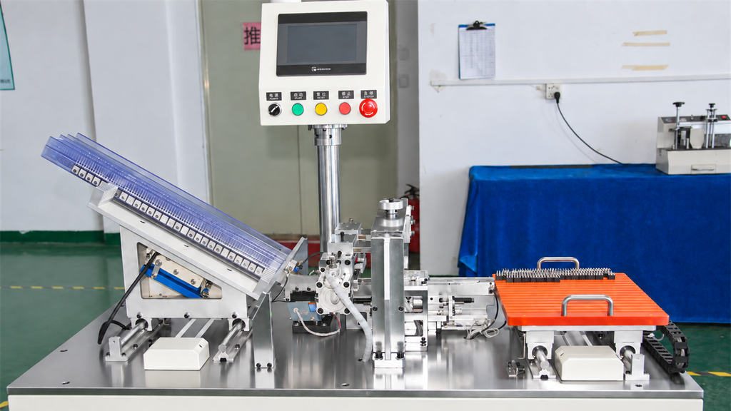
The FL-955 Automatic Transistor Lead Forming Machine is designed mainly for bulk components and can also be customized for tube feeding.
Bulk parts are fed through a vibratory bowl and linear track. The machine can install up to six forming-die sets, allowing different forming specifications to be switched without removing every die.
Suitable for:
- Bulk TO-220 components
- Automatic feeding and collection
- Several regularly used forming shapes
- Production that needs reduced operator involvement
Advantages:
- Automatic bulk feeding
- Up to six forming-die positions
- Easier switching between regularly used forming shapes
- Automatic counting and collection
- PLC and touchscreen control
- Less manual handling during continuous production
Limitations:
- Larger footprint and higher investment
- The vibratory bowl and track must be customized for the actual component
- Package variation can affect feeding stability
- The nominal speed is lower than the FL-951 because the machine focuses on automated feeding and multi-die flexibility
- Not cost-effective for prototypes or low-volume production
Is the FL-950 Suitable for TO-220?
The FL-950 Transistor Lead Forming Machine has a published speed of approximately 3,600–4,500 pieces per hour and uses vibratory feeding with separator positioning.
However, the current product description identifies it primarily as a machine for TO-92 packaged components. It should therefore not be presented as the first recommendation for TO-220 unless a customized feeding system and forming die have been evaluated with actual samples.
This distinction is important. “Transistor lead forming machine” does not mean that every transistor package can run on the same equipment.
Quick Machine Selection
| Production requirement | Recommended model | Main reason |
|---|---|---|
| TO-220 sampling or customized small batches | FL-952 | Flexible pneumatic forming and customized tooling |
| Tube-packaged power transistors or IGBTs | FL-952 | Designed for tube-type power devices |
| Standard forming shape with higher output | FL-951 | Higher published processing speed |
| Bulk components requiring automatic feeding | FL-955 | Vibratory bowl, automatic transfer, and collection |
| Several frequently used forming shapes | FL-955 | Supports up to six forming-die positions |
| Primarily TO-92 components | FL-950 | Designed mainly for smaller TO-92 packages |
| Forming followed by heatsink fastening | FL-915 or FL-915A series | Integrates transistor forming with heatsink assembly |
If lead forming is immediately followed by insulation-pad placement, heatsink positioning, or screw fastening, a separate lead former may not be the most efficient solution. In that case, the FL-915 or FL-915A integrated assembly equipment should also be evaluated.
Frequently Asked Questions
No universal assumption should be made. A machine platform may support several TO-220 devices, but package dimensions, lead count, lead thickness, incoming packaging, and final geometry can require different guides, clamps, cutters, or forming dies. Each target part number should be reviewed.
No. Cutting or trimming controls lead length. Forming changes lead geometry through bending, offsetting, spreading, or another controlled operation. A cut-and-form machine performs both functions, but the process sequence and tooling remain application-specific.
There is no single value that should be applied to every TO-220 device. Use the current package drawing and assembly guidance from the selected component manufacturer. Published guidance for one package construction may not apply to another supplier, full-pack version, or lead geometry.
Either sequence may be valid. The decision depends on how the leads are supported, the required cut datum, burr control, tooling access, and whether a finished bend could be distorted during a later cutting operation. The sequence should be verified through a tooling trial.
Tube feeding is generally preferable when the production component already arrives in consistent tubes and orientation must be preserved with limited part-on-part handling. Bulk feeding may support continuous high-volume loading, but its suitability depends on whether the component can be oriented reliably without unacceptable cosmetic or mechanical contact.
Inspection should reference an approved drawing and defined datums. Typical controls include bend-start distance, angle, radius, lead length, pitch, offset, tip alignment, burr condition, and surface damage. The measuring method must be capable of resolving the specified tolerance without deforming the part.